
Manual


CUTMASTER 10MM, 12MM
INSTALLATION 3-2 Manual 0-5197AD
3.03 Air Supply Connections
A. Connecting Air Supply to Unit
The connection is the same for compressed air or indus-
trial compressed air in gas cylinders.
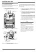
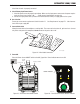
1. Connect the gas line to the compressed air inlet
port at the appropriate pressure.
Art # A-10223
Air Inlet, 1/4” NPT
On/Off
Switch
Figure 3-1 - Gas Connection to Compressed Air Input
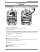
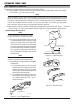
1/4 NPT
Hose Fitting
Hose
Clamp
Gas Supply Hose
Filter Hose
Single-Stage
Filter Kit
No. 7-7507
ART# A-10675
Figure 3-2 - Optional Single - Stage Filter Installation for
Compressed Air Input
B. Using Industrial Compressed Air In Gas Cylinders
When using industrial compressed air in gas cylinders
as the gas supply:
1. Refer to the manufacturer’s specifications for
installation and maintenance procedures for high
pressure gas regulators.
2. Examine the cylinder valves to be sure they are
clean and free of oil, grease or any foreign mate-
rial.Brieyopeneachcylindervalvetoblowout
any dust which may be present.
3. The cylinder must be equipped with an adjust-
able high-pressure regulator capable of outlet
pressures up to 100 psi (6.9 bar) maximum and
owsofatleast250scfh[Standardcubicfoot
perhour](120lpm)[literperminute].
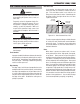
4. Connect gas supply hose to the cylinder.
NOTE
Pressure should be set at 100 psi (6.9 bar) at
the high pressure gas cylinder regulator.
Supply hose must be at least 1/4 inch (6mm)
internal diameter.
For a secure seal, apply thread sealant to the
fitting threads, according to manufacturer's
instructions. DO NOT useTeon tapeasa
thread sealer, as small particles of the tape
may break off and block the small gas pas
-
sages in the torch.