30i TRANSarc welding Inverter A-11843 Service Manual Revision: AA Issue Date: February 18, 2013 Operating Features: Manual No.
WE APPRECIATE YOUR BUSINESS! Congratulations on your new Cigweld product. We are proud to have you as our customer and will strive to provide you with the best service and reliability in the industry. This product is backed by our extensive warranty and world-wide service network. To locate your nearest distributor or service provider call +1300 654 674, or visit us on the web at www.cigweld.com.
! WARNINGS Read and understand this entire Manual and your employer’s safety practices before installing, operating, or servicing the equipment. While the information contained in this Manual represents the Manufacturer’s best judgement, the Manufacturer assumes no liability for its use.
TABLE OF CONTENTS SECTION 1: ARC WELDING SAFETY INSTRUCTIONS AND WARNINGS...................................... 1-1 1.01 1.02 1.03 1.04 1.05 1.06 Arc Welding Hazards........................................................................................ 1-1 Principal Safety Standards............................................................................... 1-5 Declaration of Conformity................................................................................ 1-6 Symbol Chart.....................
TABLE OF CONTENTS 6.11 6.12 6.13 6.14 DIP switch settings, Control PCB................................................................... 6-13 Calibration..................................................................................................... 6-14 Main Circuit Description................................................................................ 6-16 Circuit Diagram..............................................................................................
TRANSARC 130i SECTION 1: ARC WELDING SAFETY INSTRUCTIONS AND WARNINGS ! WARNING PROTECT YOURSELF AND OTHERS FROM POSSIBLE SERIOUS INJURY OR DEATH. KEEP CHILDREN AWAY. PACEMAKER WEARERS KEEP AWAY UNTIL CONSULTING YOUR DOCTOR. DO NOT LOSE THESE INSTRUCTIONS. READ OPERATING/INSTRUCTION MANUAL BEFORE INSTALLING, OPERATING OR SERVICING THIS EQUIPMENT.
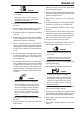
TRANSARC 130i 2. Wear approved safety glasses. Side shields recommended. WARNING ARC RAYS can burn eyes and skin; NOISE can damage hearing. Arc rays from the welding process produce intense heat and strong ultraviolet rays that can burn eyes and skin. Noise from some processes can damage hearing. 1. Use a Welding Helmet or Welding Faceshield fitted with a proper shade of filter (see ANSI Z49.1 and AS 1674 listed in Safety Standards) to protect your face and eyes when welding or watching. 3.
TRANSARC 130i 3. Remove all flammables within 35 ft (10.7 m) of the welding arc. If this is not possible, tightly cover them with approved covers. WARNING 4. Be alert that welding sparks and hot materials from welding can easily go through small cracks and openings to adjacent areas. FUMES AND GASES can be hazardous to your health. Welding produces fumes and gases. Breathing these fumes and gases can be hazardous to your health. 5. Watch for fire, and keep a fire extinguisher nearby. 6.
TRANSARC 130i 5. Use only correct shielding gas cylinders, regulators, hoses, and fittings designed for the specific application; maintain them and associated parts in good condition. 6. Turn face away from valve outlet when opening cylinder valve. 7. Keep protective cap in place over valve except when cylinder is in use or connected for use. 8. Read and follow instructions on compressed gas cylinders, associated equipment, and CGA publication P-1 listed in Safety Standards.
TRANSARC 130i 1.02 Principal Safety Standards Safety in Welding and Cutting, ANSI Standard Z49.1, from American Welding Society, 550 N.W. LeJeune Rd., Miami, FL 33126. Safety and Health Standards, OSHA 29 CFR 1910, from Superintendent of Documents, U.S. Government Printing Office, Washington, D.C. 20402. Recommended Safe Practices for the Preparation for Welding and Cutting of Containers That Have Held Hazardous Substances, American Welding Society Standard AWS F4.1, from American Welding Society, 550 N.W.
TRANSARC 130i 1.03 Declaration of Conformity Manufacturer: CIGWELD Address: 71 Gower St, Preston Victoria 3072 Australia Description of equipment: Welding Equipment (GTAW, MMAW) including, but not limited to CIGWELD Transarc 130i Welding Inverter and associated accessories. Serial numbers are unique with each individual piece of equipment and details description, parts used to manufacture a unit and date of manufacture.
TRANSARC 130i 1.04 Symbol Chart Note that only some of these symbols will appear on your model. On Single Phase Wire Feed Function Off Three Phase Wire Feed Towards Workpiece With Output Voltage Off.
TRANSARC 130i • Use proper static-proof bags and boxes to store, move, or ship PC boards. 1.05 Servicing Hazards ! WARNING WARNING The symbols shown below are used throughout this manual to call attention to and identify possible hazards. When you see the symbol, watch out, and follow the related instructions to avoid the hazard. FIRE OR EXPLOSION hazard. • Do not place unit on, over, or near combustible surfaces. • Do not service unit near flammables.
TRANSARC 130i • High-frequency (H.F.) can interfere with radio navigation, safety services, computers, and communications equipment. WARNING • Have only qualified persons familiar with electronic equipment install, test, and service H.F. producing units. FALLING UNIT can cause injury. • Use lifting eye to lift unit only, NOT running gear, gas cylinders, or any other accessories.
TRANSARC 130i 1.06 EMF Information Considerations About Welding And The Effects Of Low Frequency Electric And Magnetic Fields Welding current, as it flows through welding cables, will cause electromagnetic fields. There has been and still is some concern about such fields.
TRANSARC 130i SECTION 2: INTRODUCTION 2.01 How to Use This Manual 2.03 Receipt of Equipment To ensure safe operation, read the entire manual, including the chapter on safety instructions and warnings. When you receive the equipment, check it against the invoice to make sure it is complete and inspect the equipment for possible damage due to shipping. If there is any damage, notify the carrier immediately to file a claim.
transarc 130i Notes INTRODUCTION 2- 2 Manual 0-5282
TRANSARC 130i SECTION 3: SAFETY AND INSTALLATION 3.01 Duty Cycle The rated duty cycle of a Welding Power Source, is a statement of the time it may be operated at its rated welding current output without exceeding the temperature limits of the insulation of the component parts. To explain the 10 minute duty cycle period the following example is used. Suppose a Welding Power Source is designed to operate at a 25% duty cycle, 130 amperes at 25.2 volts.
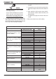
TRANSARC 130i 3.02 Specifications Description Transarc 130i Plant Part No W1007130 Plant Part No (Mine Spec) W1007131 W1007129 H306mmxW121mmxD376mm 7 KG Fan Cooled Multi Process Inverter Power Source AS 60974.1-2006 / IEC 60974.
TRANSARC 130i Due to large variations in performance and specifications of different brands and types of generators, Cigweld cannot guarantee full welding output power or duty cycle on every brand or type of generator. Some small generators incorporate low cost circuit breakers on their outputs. These circuit breakers usually will have a small reset button, and will trip much faster than a switchboard type circuit breaker.
TRANSARC 130i 3.07 Electromagnetic Compatibility 3.05 High Frequency Introduction The importance of correct installation of high frequency welding equipment cannot be overemphasized. Interference due to high frequency initiated or stabilised arc is almost invariably traced to improper installation. The following information is intended as a guide for personnel installing high frequency welding machines.
TRANSARC 130i 6. Equipment used for calibration and measurement. 7. The time of day that welding or other activities are to be carried out. 8. The immunity of other equipment in the environment: the user shall ensure that other equipment being used in the environment is compatible: this may require additional protection measures. The size of the surrounding area to be considered will depend on the structure of the building and other activities that are taking place.
TRANSARC 130i Notes SAFETY AND INSTALLATION 3-6 Manual 0-5282
TRANSARC 130i SECTION 4: INSTALLATION, OPERATION AND SETUP 4.01 Transarc 130i Power Source Controls, Indicators and Features A-11743 A-11733 Figure 4-1: Front Panel Figure 4-2: Rear Panel 1. VRD ON/OFF Indicator Lights A VRD (voltage reduction device) is a hazard reducing device designed to reduce electric shock hazards present on the output of welding power source when operating in MMAW (stick) mode.
TRANSARC 130i Fail to safe operation This welding power source is also protected by a special protection feature called “Fail to Safe Operation” which is available in all welding modes. The output of the power source will be disabled and the fault indicator will illuminate if the “Fail to Safe” protection has operated.. The “Fail to Safe” protection will not automatically reset. The mains power switch must be turned off to reset the power source.
TRANSARC 130i A-11734 Figure 4-3: Programming Mode STICK Programming Mode Programming Parameter Control Panel Display Hot Start This parameter operates in STICK mode to improve the start characteristics for stick electrodes HOT START current is on top of the BASE current. e.g. HOT START current = 130 amps when BASE (WELD) = 100 amps & HOT START = 30 amps Range is 0 to 70A. Factory default is 20A. Note that maximum weld current is 170A. Base Current This parameter sets the STICK weld current.
TRANSARC 130i Programming Parameter Control Panel Display Arc Force Arc Force is effective when in STICK mode only. Arc Force control provides an adjustable amount of Arc Force (or "dig") control. This feature can be particularly beneficial in providing the operator the ability to compensate for variability in joint fit-up in certain situations with particular electrodes. In general increasing the Arc Force control toward 100% (maximum Arc Force) allows greater penetration control to be achieved.
TRANSARC 130i Base Current This parameter sets the TIG welding current. Range is 5 to 130A. Factory default is 120A. Down Slope This parameter operates in TIG mode only and is used to set the time for the weld current to ramp down to the crater current. This control is used to eliminate the crater that can form at the completion of a weld. Range is 0.0 to 25.0 seconds. Factory default is 3.0 seconds. Crater Current This parameter operates in TIG mode only.
TRANSARC 130i Post Flow This parameter operates in TIG mode only and is used to adjust the post gas flow time once the arc has extinguished. This control is used to dramatically reduce oxidation of the tungsten electrode. Range is 0.0 to 30.0 seconds. Factory default is 5.0 seconds. 5. Positive Welding Output Terminal The positive welding terminal is used to connect the welding output of the power source to the electrode holder lead or work lead.
TRANSARC 130i Socket Pin Function 1 Not connected 2 Trigger Switch Input 3 Trigger Switch Input 4 Not connected 5 5k ohm (maximum) connection to 5k ohm remote control potentiometer. 6 Zero ohm (minimum) connection to 5k ohm remote control potentiometer. 7 Wiper arm connection to 5k ohm remote control Amps GTAW (TIG) mode potentiometer. 8 Not connected. Table 4-1 8.
TRANSARC 130i A-11725 STICK Dead Man Switch Mode A special trigger mode called “Dead Man Switch” mode is available on the 130i when welding with STICK electrodes. In this mode, there will be no output voltage at all from the Power Source until the trigger is pressed. This provides the greatest level of safety for the operator, and is mandatory on some work sites. While the Dead Man Switch function greatly increases operator safety, standard welding safety procedures should still be followed.
TRANSARC 130i A-11745 There will be 0V on the Power Source welding terminals and both VRD lights will be off. In both 2T and 4T modes, if the stick electrode is not touched to the work piece within three seconds, the welding output will be inhibited. Release the trigger to reset, and press the trigger again to reactivate the VRD. Note that if the Dead Man Switch function is disabled, 2T and 4T are not available in STICK mode.
TRANSARC 130i 10. Process Selection Control The process selection control is used to select the desired welding mode. Two modes are available, GTAW (Lift TIG) and MMAW (Stick) modes. Refer to section 4.03 for GTAW (TIG) set-up details or section 4.04 for MMAW (stick) set-up details. Note that when the unit is powered on the mode selection control will automatically default to LIFT TIG mode.
TRANSARC 130i 4.02 Shielding Gas Regulator Operating Instructions (where supplied) ! WARNING This equipment is designed for use with welding grade (Inert) shielding gases only. Shielding Gas Regulator Safety This regulator is designed to reduce and control high pressure gas from a cylinder or pipeline to the working pressure required for the equipment using it. If the equipment is improperly used, hazardous conditions are created that may cause accidents.
TRANSARC 130i Installation 1. Remove cylinder valve plastic dust seal. Clean the cylinder valve outlet of impurities that may clog orifices and damage seats before connecting the regulator. Crack the valve (open then close) momentarily, pointing the outlet away from people and sources of ignition. Wipe with a clean lint free cloth. 2. Match regulator to cylinder. Before connecting, check that the regulator label and cylinder marking agree and that the regulator inlet and cylinder outlet match.
TRANSARC 130i Shutdown Close cylinder valve whenever the regulator is not in use. To shut down for extended periods (more than 30 minutes). 1. Close cylinder or upstream valve tightly. 2. Open downstream equipment valves to drain the lines. Bleed gas into a well ventilated area and away from any ignition source. 3. After gas is drained completely, disengage adjusting screw and close downstream equipment valves. 4.
TRANSARC 130i Figure 4-7: Setup for TIG Welding 4.04 Foot Control Part No.
TRANSARC 130i Pin Description 1 Not Used 2 Trigger Switch 3 Trigger Switch 4 Not Used 5 Potentiometer Maximum 6 Potentiometer Minimum 7 Potentiometer Wiper 8 Not Used Table 4-2 Description The CIGWELD Foot Control is a foot operated switch and potentiometer which starts and stops the welding process and controls welding current through operation of the foot pedal. Refer to list below for compatible Cigweld power sources.
TRANSARC 130i 4.05 Setup for Manual Arc (MMAW) Welding A. Connect the Electrode Holder lead to the positive welding terminal (+). If in doubt, consult the electrode manufacturer. Welding current flows from the Power Source via heavy duty bayonet type terminals. It is essential, however, that the male plug is inserted and turned securely to achieve a sound electrical connection. B. Connect the work lead to the negative welding terminal (-). If in doubt, consult the electrode manufacturer.
TRANSARC 130i SECTION 5: THEORY OF OPERATION 5.01 Inverter Design What does the word inverter mean? The term inverter refers to the ability to change DC power into AC. Inverter power supplies immediately rectify the incoming AC to DC, and then the transistors create a higher frequency AC. The higher frequency AC then goes on to a much smaller main transformer than in a conventional power supply. The AC is then rectified to extremely smooth DC.
TRANSARC 130i Notes THEORY OF OPERATION 5-2 Manual 0-5282
TRANSARC 130i SECTION 6: TROUBLESHOOTING 6.01 Basic Troubleshooting-Power Source Faults The following table is a guide for analyzing problems and making repairs to the Power Source.
TRANSARC 130i 6 Weld Output operates when A the torch trigger switch is depressed but the gas valve does not operate. B C Internal wiring fault D Faulty Solenoid Impurity in gas system causing solenoid to stay open or closed Faulty Power Inverter board E Faulty Control board A Check solenoid wiring header is plugged securely into Control board. Check solenoid wiring is not damaged B Replace Solenoid C Clean out gas system.
TRANSARC 130i 6.03 Advanced Troubleshooting If the problem cannot be solved by the basic (external) troubleshooting guide, the Power Source cover will have to be removed to allow the technician to analyze failures with a few common tools. ! WARNING Turn off power and disconnect mains supply plug from receptacle before working on the unit. Allow two minutes for capacitors to discharge after disconnection from mains supply voltage.
TRANSARC 130i 6.06 Preliminary DC Bus measurement of the main inverter board ! WARNING Check DC bus voltage has discharged to less than 5VDC before servicing. Ensure the mains supply plug is disconnected from receptacle.
TRANSARC 130i 6.07 Preliminary check of the main inverter board ! Read and follow safety information in Section 6.03 before proceeding. A-11845 IGBT Testing IGBT V8 IGBT T1 IGBT T4 Multimeter Lead Placement Positive meter lead to testpoint 3 Negative meter lead to testpoint 4 Positive meter lead to testpoint 5 Negative meter lead to testpoint 6 Positive meter lead to testpoint 7 Negative meter lead to testpoint 8 Diode Voltage 0.2 – 0.8 VDC 0.2 – 0.8 VDC 0.2 – 0.
TRANSARC 130i IGBT Testing IGBT V8 & V8-1 IGBT T1 & T2 IGBT T4 & T5 Inrush Resistor Resistor Multimeter Lead Placement Positive meter lead to testpoint 4 Negative meter lead to testpoint 3 Positive meter lead to testpoint 6 Negative meter lead to testpoint 5 Positive meter lead to testpoint 8 Negative meter lead to testpoint 7 Table 6-4: IGBT’s, Multimeter set to measure ohms (Ω) Ohms >150 Ω Multimeter Lead Placement Positive meter lead to testpoint 9 Negative meter lead to testpoint 10 Table 6-5: Inrus
TRANSARC 130i Input Rectifier Testing AC1 to DC+ Multimeter Lead Placement Positive meter lead to testpoint 17 Negative meter lead to testpoint 18 Diode Voltage 0.2 – 0.8 VDC AC2 to DC+ Positive meter lead to testpoint 19 0.2 – 0.8 VDC Negative meter lead to testpoint 18 AC1 to DCPositive meter lead to testpoint 17 0.2 – 0.8 VDC Negative meter lead to testpoint 20 AC2 to DCPositive meter lead to testpoint 19 0.2 – 0.
TRANSARC 130i DC Bus Testing Multimeter Lead Placement Upper capacitor bank Positive meter lead to testpoint 1 Negative meter lead to testpoint 2 Lower capacitor bank Positive meter lead to testpoint 2 Negative meter lead to testpoint 3 Overall capacitor bank Positive meter lead to testpoint 1 Negative meter lead to testpoint 3 Table 6-8: DC BUS, Multimeter set to measure DC volts Voltage with Supply voltage OFF 150-200 VDC 150-200 VDC 300-400 VDC Note: These DC voltages are at nominal mains supply vol
TRANSARC 130i IN Header Pin 1 2 3 4 5 6 7 Pin function +15 IGBT 1 pwm drive signal, 15V p-p square wave IGBT 2 pwm drive signal, 15V p-p square wave IGBT 2 pwm drive signal, 15V p-p square wave IGBT 1 pwm drive signal, 15V p-p square wave Rectified secondary of current transformer TR8 0V signal 15 VDC 15 VDC pk 15 VDC pk 15 VDC pk 15 VDC pk 15 VDC pk 0 VDC Table 6-9: IN Header pin function (connects to DRIVE header on control PCB) DY2 Header Pin 1 2 3 Pin function +24 VDC 0 VDC -24V signal 24 VDC 0 VDC
TRANSARC 130i 2 Display PCB A-11849 J12 Header Pin Pin function signal 1 Serial display data (LOAD) 5 VDC digital 2 Serial display data & eprom (D-IN) 5 VDC digital 3 Serial diaplay data (CLK) 5 VDC digital 4 Serial display eprom (D-OUT) 5 VDC digital 5 DeadMan Switch (5V in Dead Man mode) 5 VDC digital 6 Encoder Output "A" (pulse output) 5 VDC digital 7 Encoder Output "D" (button) 5 VDC digital 8 Encoder direction 5 VDC digital 9 2T/4T push button (0v when button pushed) 5 VDC 10 MODE push button (0v wh
TRANSARC 130i 3 Control PCB A-11850 WV Header Pin 1 2 3 Pin function Positive welding terminal No connection Negative welding terminal Table 6-15: WVIN Header pin function signal Positive VDC n/c 0 VDC GUN Header Pin Pin function signal 1 Trigger 8 pin socket, pin 3 0 VDC 2 Trigger 8 pin socket, pin 2 3 Remote Amps Pot, 8 pin socket, pin 5 4 Remote Amps Pot, 8 pin socket, pin 6 5 Trigger 8 pin socket, pin 3 0 VDC Table 6-16: GUN Header pin function (connects to remote 8 pin socket on front of power so
TRANSARC 130i MB Header Pin Pin function signal 1 Serial display data (LOAD) 5 VDC digital 2 Serial display data & eprom (D-IN) 5 VDC digital 3 Serial diaplay data (CLK) 5 VDC digital 4 Serial display eprom (D-OUT) 5 VDC digital 5 DeadMan Switch (5V in Dead Man mode) 5 VDC digital 6 Encoder Output "A" (pulse output) 5 VDC digital 7 Encoder Output "D" (button) 5 VDC digital 8 Encoder direction 5 VDC digital 9 2T/4T push button (0v when button pushed) 5 VDC 10 MODE push button (0v when button pushed) 5 VDC 11
TRANSARC 130i 6.
TRANSARC 130i 6.12 Calibration 1 Calibration A-11853 While the power source is turned off, set SW1 position 2 to OFF, to allow calibration of output volts & amps. 2 Output Current Calibration Select STICK mode on the front panel. Connect a load to the output terminals. The load should be of a resistance to give between 20V – 25V at 130A. Set front panel AMPS control to minimum. Adjust Imin trimpot until output amps is 5A +/- 0.5A Set front panel AMPS control to maximum.
TRANSARC 130i 3 Remote Calibration Select LIFT TIG mode on the front panel. Remove the load from the output terminals. Set front panel AMPS control to maximum. Connect a remote control device and set the remote control potentiometer to maximum.
TRANSARC 130i 6.13 Main Circuit Description ! WARNING Turn off power and disconnect mains supply plug from receptacle before working on the unit. Allow two minutes for capacitors to discharge after disconnection from mains supply voltage. A-11854 The mains supply voltage is connected via a double pole switch to the input rectifiers on the main inverter board through an EMC filter. Overvoltage protection is provided by varistor CY1.
TRANSARC 130i 6.
TRANSARC 130i Notes TROUBLESHOOTING 6-18 Manual 0-5282
TRANSARC 130i SECTION 7: DISASSEMBLY PROCEDURE 7.01 Safety Precautions for Disassembly ! ! Read and follow safety information in Section 6.02 before proceeding. Unplug unit before beginning Disassembly procedure. 7.02 Case Removal ! Read and follow safety information in Section 6.03 before proceeding with disassembly 1. Unscrew 12 Screws to disassemble two parts of case. Remove the case.
TRANSARC 130i 7.03 Control PCB Removal ! Read and follow safety information in Section 6.03 before proceeding with disassembly Remove case (refer to 7.02) before removing the control board. 1. Remove 2 screws from control PCB. 2 Disconnect WV harness from WV connector. 3. Disconnect GUN harness from GUN connector 4. Disconnect DY harness from DY connector. 5. Disconnect FAN harness from FAN connector. 6. Disconnect QF harness from QF connector. 7. Disconnect MB harness from MB connector. 8.
TRANSARC 130i 7.04 Solenoid Valve and Current Transformer Output Removal ! Read and follow safety information in Section 6.03 before proceeding with disassembly 1. Unplug control wire. 2. Dismantle two clips over the hose. 3. Unscrew the nut. Then the solenoid valve is disassembled. 4. Disconnect the weld cable from the welding output terminal. 5. Unplug the Current Transformer Output control wire. 6. Then the Current Transformer Output is disassembled.
TRANSARC 130i 7.05 Display PCB Removal ! Read and follow safety information in Section 6.03 before proceeding with disassembly 1. Remove Display PCB Screws. 2. Unscrew the set screw to remove the knob. 3. Unplug the harness. 4.
TRANSARC 130i 7.06 Front Panel assembly Removal ! Read and follow safety information in Section 6.03 before proceeding with disassembly 1. Remove front panel screws. 2. Remove Positive Output Terminal Bolt. 3. Remove Negative Output Terminal Bolt. 4. Disconnect hose from outlet. 5. Remove 8 pin remote control harness from the control pcb.
TRANSARC 130i 7.07 Rear Panel Removal ! Read and follow safety information in Section 6.03 before proceeding with disassembly 1. Remove 2 screws on rear panel. 2. Remove On/Off Switch wire. 3. Remove gas hose from gas inlet. 4. Remove ground screw. 5. Remove fan screws to disassemble the fan. 6. Remove power Cord by push the clip. 7. Remove On/Off switch by push the clip.
TRANSARC 130i 7.08 Base Panel Removal ! Read and follow safety information in Section 6.03 before proceeding with disassembly 1. Remove 4 screws to disassemble the base panel. 2. Remove input rectifier only if it is faulty and needs to be replaced.
TRANSARC 130i Notes DISASSEMBLY PROCEDURE 7-8 Manual 0-5282
TRANSARC 130i SECTION 8: ASSEMBLY PROCEDURES 8.01 Installing Base Panel 1. Install input rectifier if it is removed. 2. Install base panel screws to assemble the base panel.
TRANSARC 130i 8.02 Installing Rear Panel 1. Reinstall on/off switch. 2. Reinstall power cord. 3. Reinstall fan. install 4 screws. 4. Reinstall ground wire. 5. Reinstall gas hose to gas inlet. 6. Reinstall input wire. 7. Reinstall rear panel 2 screws to install rear panel.
TRANSARC 130i 8.03 Installing Front Panel assembly 1. Reinstall Positive Output Terminals Bolt. 2. Reinstall Negative Output Terminals. 3. Reinstall gas hose to gas outlet. 4. Reinstall 8 pin wire. 5. Reinstall 2 screws to install front panel.
TRANSARC 130i 8.04 Installing Display PCB 1. Plug the ribbon cable into the socket, make sure it is correctly installed with the levers in the locked position. 2. Reinstall three screws to install display PCB. 3. Reinstall set screw to install knob. 4. Install the 4 screws.
TRANSARC 130i 8.05 Installing Solenoid Valve and Current Transformer Output 1. Reinstall Current Transformer Output. 2. Connect the control wire to Current Transformer Output. 3. Connect the weld cable to the welding output terminal. 4. Install the two clips over the gas hose. 5. Install the screw to install the solenoid value. 5. Plug the wire for solenoid valve.
TRANSARC 130i 8.06 Installing Control PCB 1. Install 2 screws on control PCB. 2 Plug WV harness to WV connector. 3. Plug GUN harness to GUN connector 4. Plug DY harness to DY connector. 5. Plug FAN harness to FAN connector. 6. Plug QF harness to QF connector. 7. Plug MB harness to MB connector. 8. Plug OT2 harness to OT2 connector. 9. Plug OT1 harness to OT1 connector. 10. Plug IFB harness to IFB connector. 11. Plug DRIVE harness to DRIVE connector. 12. Plug SOURCE harness to SOURCE connector.
TRANSARC 130i 8.07 Installing Case 1. Install 12 screws to install the case.
TRANSARC 130i Notes ASSEMBLY PROCEDURES 8-8 Manual -5282
TRANSARC 130i SECTION 6: KEY SPARE PARTS 9.
TRANSARC 130i TRANSARC 130i POWER SOURCE SPARE PARTS ITEM 1 2 3 4 5 PART NUMBER W7005808 W7005807 W7005809 W7005810 W7003019 6 W7005811 7 8 9 10 11 12 13 14 15 W7005812 W7005814 W7004908 W7005605 W7005813 W7004913 W7003004 W7003010 705152 DESCRIPTION PCB Power PCB Control 130i PCB Front Panel (Display) 130i Knob Control Dinse Socket 25mm2 Control Socket 8 pin (Note that 8 pin control plug is part number UOA706900) Shielding Gas Outlet 5/8-18 CT Output Shielding Gas Solenoid Valve Assembly Shielding Ga
TRANSARC 130i 9.03 Stick Electrode Holder with Trigger Switch 646762(where supplied) Stick Electrode Holder with Trigger Switch 646762 spare parts diagram A-11710 Figure 9-3 ELECTRODE HOLDER SPARE PARTS ITEM PART NO.
TRANSARC 130i Notes KEY SPARE PARTS 6-4 Manual 0-5282
CIGWELD - LIMITED WARRANTY TERMS LIMITED WARRANTY: CIGWELD Pty Ltd, A Victor Technologies Company, hereafter, “CIGWELD” warrants to customers of its authorized distributors hereafter “Purchaser” that its products will be free of defects in workmanship or material.
TERMS OF WARRANTY – January 2013 1. The Trade Practices Act 1974 (Commonwealth) and similar State Territory legislation relating to the supply of goods and services, protects consumers’ interests by ensuring that consumers are entitled in certain situations to the benefit of various conditions, warranties, guarantees, rights and remedies (including warranties as to merchantability and fitness for purpose) associated with the supply of goods and services.
WARRANTY SCHEDULE – January 2013 These warranty periods relate to the warranty conditions in clause 2. All warranty periods are from date of sale from the Accredited Distributor of the equipment. Notwithstanding the foregoing, in no event shall the warranty period extend more than the time stated plus one year from the date CIGWELD delivered the product to the Accredited Distributor. Unless otherwise stated the warranty period includes parts and labour.
Australia Terms of Warranty – 2013 Effective 1st January 2012, all warranties against defects (also known as a manufacturer’s warranty) supplied with goods or services must comply with the new Australian consumer law regulations (2010). This Warranty Statement should be read in conjunction with the Warranty Schedule contained in the operating instructions of the product.
GLOBAL CUSTOMER SERVICE CONTACT INFORMATION CIGWELD, Australia 71 Gower Street Preston, Victoria Australia, 3072 Telephone: 61-3-9474-7400 Fax: 61-3-9474-7391 Email: enquiries@cigweld.com.au Victor Technologies USA 2800 Airport Road Denton, Tx 76207 USA Telephone: (940) 566-2000 800-426-1888 Fax: 800-535-0557 Email: sales@thermalarc.
Asia Pacific Regional Headquarters 71 Gower Street Preston, Victoria, Australia, 3072 Telephone: +61 3 9474 7400 +61 3 9474 7391 FAX: Email: enquiries@cigweld.com.au www.cigweld.com.