51 CUTMASTER ™ PLASMA CUTTING SYSTEM Art # A-06754 Operating Manual Rev. AC.
WE APPRECIATE YOUR BUSINESS! Congratulations on your new Thermal Dynamics product. We are proud to have you as our customer and will strive to provide you with the best service and reliability in the industry. This product is backed by our extensive warranty and world-wide service network. To locate your nearest distributor or service agency call 1-800426-1888, or visit us on the web at www.thermal-dynamics.com.
WARNINGS Read and understand this entire Manual and your employer’s safety practices before installing, operating, or servicing the equipment. While the information contained in this Manual represents the Manufacturer's best judgement, the Manufacturer assumes no liability for its use. Plasma Cutting Power Supply CutMaster™ 151 Operating Manual Number 0-4668 Covered under U.S. Patents Published by: Thermal Dynamics Corporation 82 Benning Street West Lebanon, New Hampshire, USA 03784 (603) 298-5711 www.
TABLE OF CONTENTS SECTION 1: GENERAL INFORMATION ................................................................................................ 1-1 1.01 1.02 1.03 1.04 1.05 Notes, Cautions and Warnings ...................................................................... Important Safety Precautions ....................................................................... Publications ..................................................................................................
TABLE OF CONTENTS (continued) PATENT INFORMATION ............................................................................................................ 6-4 APPENDIX 1: SEQUENCE OF OPERATION (BLOCK DIAGRAM) .......................................................................................................... A-1 APPENDIX 2: DATA TAG INFORMATION ................................................................................ A-2 APPENDIX 3: MAINTENANCE SCHEDULE ......................................
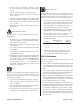
SECTION 1: GENERAL INFORMATION 1.01 Notes, Cautions and Warnings GASES AND FUMES Gases and fumes produced during the plasma cutting process can be dangerous and hazardous to your health. • Keep all fumes and gases from the breathing area. Keep your head out of the welding fume plume. Throughout this manual, notes, cautions, and warnings are used to highlight important information.
• Wear dry gloves and clothing. Insulate yourself from the work piece or other parts of the welding circuit. • Repair or replace all worn or damaged parts. • Extra care must be taken when the workplace is moist or damp. • Install and maintain equipment according to NEC code, refer to item 9 in Subsection 1.03, Publications. PLASMA ARC RAYS Plasma Arc Rays can injure your eyes and burn your skin. The plasma arc process produces very bright ultra violet and infra red light.
6. ANSI Standard Z49.2, FIRE PREVENTION IN THE USE OF CUTTING AND WELDING PROCESSES, obtainable from American National Standards Institute, 1430 Broadway, New York, NY 10018 7. AWS Standard A6.0, WELDING AND CUTTING CONTAINERS WHICH HAVE HELD COMBUSTIBLES, obtainable from American Welding Society, 550 N.W. LeJeune Rd, Miami, FL 33126 8.
1.04 Declaration of Conformity Manufacturer: Thermal Dynamics Corporation Address: 82 Benning Street West Lebanon, New Hampshire 03784 USA The equipment described in this manual conforms to all applicable aspects and regulations of the ‘Low Voltage Directive’ (European Council Directive 73/23/EEC as amended by Council Directive 93/68/EEC) and to the National legislation for the enforcement of this Directive.
1.05 Statement of Warranty LIMITED WARRANTY: Subject to the terms and conditions established below, Thermal Dynamics® Corporation warrants to the original retail purchaser that new Thermal Dynamics CUTMASTER™ 1Series plasma cutting systems sold after the effective date of this warranty are free of defects in material and workmanship.
This Page Left Blank GENERAL INFORMATION 1-6 October 5, 2006
SECTION 2: INTRODUCTION 2.01 Scope of Manual This manual contains descriptions, operating instructions and basic maintenance procedures for the Thermal Dynamics® CutMaster™ 151 Plasma Cutting Power Supply only. Servicing of this equipment is restricted to properly trained personnel; unqualified personnel are strictly cautioned against attempting repairs or adjustments not covered in this manual, at the risk of voiding the Warranty. Read this manual thoroughly.
Power Supply Dimensions & Weight Ventilation Clearance Requirements Art # A-03379 83 lb / 37.6 kg 6" 150 mm 17.3 in / 439 mm 24" 0.6 m 27.5 in / 696 mm A-03572 6" 150 mm 12.4 in / 315 mm 6" 150 mm 2.03 Input Wiring Specifications Input Voltage Freq.
2.
2.05 Power Supply Options and Accessories Section 6, Parts Lists, provides catalog numbers and ordering information. A. Single-Stage Air Filter Kit For use with compressed air shop systems. Filters moisture and particulate matter from the air stream to at least 0.85 microns. This filter increases performance and improves consumables parts life. B. Two Stage Air Filter Kit For use on compressed air shop systems. Filters moisture and contaminants from the air stream to at least 5.0 microns.
SECTION 3: INSTALLATION 3.01 Unpacking 1. Use the packing lists to identify and account for each item. 2. Inspect each item for possible shipping damage. If damage is evident, contact your distributor and / or shipping company before proceeding with the installation. 3. Record Power Supply and Torch model and serial numbers, purchase date and vendor name, in the information block at the front of this manual. 3.02 Lifting Options The Power Supply includes a handle for hand lifting only.
3.03 Primary Input Power Connections CAUTION Check your power source for correct voltage before plugging in or connecting the unit. The primary power source, fuse, and any extension cords used must conform to local electrical code and the recommended circuit protection and wiring requirements as specified in Section 2.03. A. Connections to 208 / 230 - Volt Power The 208 / 230 - Volt power supply includes a factory - installed input power cable for single - phase input power. 1.
C. Connections to 400 - Volt, and 460 - Volt Single- Phase Power The 400 - Volt or 460 - Volt Power Supplies will accept Single - Phase input power with a change of input power cable. 1. Remove the Power Supply cover per section 5.04. 2. Disconnect the original input power cable from the main input contactor and the chassis ground connection. 3. Loosen the through - hole protector on the back panel of the power supply. Pull the original power cable out of the power supply. 4.
3.04 Gas Connections A. Connecting Gas Supply to Unit Use only compressed air with this power supply. The connection is the same for compressed air from a compressor from high pressure cylinders. Refer to subsection 3.4-B or 3.4-C if an optional air line filter is to be installed. 1. Connect the air line to the inlet port. The illustration shows typical fittings as an example. Other fittings can be used.
B. Optional Air Filters 1. Connect the Filter as illustrated. Use only Synflex or equivalent grade hose. The illustrations show typical fittings as an example. NOTE For a secure seal, apply thread sealant to the fitting threads, according to the maker's instructions. Do Not use Teflon tape as a thread sealer, as small particles of the tape may break off and block the small air passages in the torch.
3.05 Torch Connections If necessary, connect the torch to the Power Supply. Connect only the Thermal Dynamics model SL60 or SL100 Torch (with ATC connector) to this power supply. Maximum torch leads length is 100 feet / 30.5 m, including extensions. WARNING If an SL60 Torch is used on this unit, do not exceed an output setting (dial on front of unit) higher than 60. WARNING Disconnect primary power at the source before connecting the torch. 1.
B. Check Air Quality To test the quality of air: 1. Put the ON / OFF switch in the ON (up) position. 2. Put the RUN / RAPID AUTO RESTART / SET switch in the SET (down) position. 3. Place a welding filter lens in front of the torch and turn on the air. Any oil or moisture in the air will be visible on the lens.
INSTALLATION 3-8 Manual 0-4668
SECTION 4: OPERATION 4.01 Product Features A. Front Panel Controls and Indicators (A) Output Current Control AC Indicator Sets the desired output current. Output settings up to 40 Amps may be used for drag cutting (with the torch tip contacting the workpiece). At output settings over 40 Amps, the power supply automatically reduces output current to 40 Amps if the tip touches the workpiece. Steady light indicates power supply is ready for operation.
4.02 Preparations For Operating Perform the following steps at the start of each operating session: WARNING Disconnect primary power at the source before assembling or disassembling power supply, torch parts, or torch and leads assemblies. A. Torch Parts Selection Check the torch for proper assembly and appropriate torch parts. The torch parts must correspond with the type of operation, and with the amperage output of this Power Supply (100 amps maximum). Refer to the Torch Manual. B.
F. Power On Place the Power Supply ON / OFF switch to the ON (up) position. AC indicator turns on. Gas indicator turns on if there is sufficient gas pressure for power supply operation. NOTE Minimum pressure for power supply operation is lower than minimum for torch operation.
G. Set Operating Pressure 1. Place the Power Supply RUN / Rapid Auto Restart / SET switch to the SET (down) position. Gas will flow. 2 1 Art # A-04254 2. Adjust gas pressure per the settings chart. 70 - 75 psi / 4.5 - 5.2 bar CutMaster™ 151 Gas Pressure Settings SL100™ Leads (Hand Torch or Length Machine Torch) Up to 25' 70 psi (7.6 m) 4.8 bar Over 25' 75 psi (7.6 m) 5.
H. Select Current Output Level 1. Place RUN / Rapid Auto Restart / SET to RUN (up) or Rapid Auto Restart (center) position. Gas flow stops. 2. Set the current output level, up to 40 amps for drag cutting (with the torch tip in contact with the workpiece), or up to 100 amps for standoff cutting. At output settings higher than 40 amps, the power supply automatically reduces output current to 40 amps if the torch tip contacts the workpiece. 2 1 Art # A-04256 I.
K. Postflow Release the trigger to stop the cutting arc. Gas continues to flow for approximately 20 seconds. During post - flow, if the user moves the trigger release to the rear and presses the trigger, the pilot arc starts. The main arc transfers to the workpiece if the torch tip is within transfer distance to the workpiece. L. Shutdown Turn the ON / OFF switch to OFF (down). All Power Supply indicators shut off. Unplug the input power cord or disconnect input power. Power is removed from the system.
SECTION 5: SERVICE 5.01 General Maintenance A. O-Ring Lubrication An O-ring on the Torch ATC Male Connector requires lubrication on a regular basis, depending on how frequently the torch is disconnected and re-connected. This will allow the O-ring to remain pliable and provide a proper seal. The O-ring will dry out, becoming hard and cracked, if the O-ring lubricant is not used on a regular basis. This can lead to potential performance problems.
B. Filter Element Replacement The Regulator/Filter Assembly is on the rear panel. For better system performance, the Regulator/Filter Assembly filter element should be checked per the Maintenance Schedule (Appendix 3), and either cleaned or replaced. 1. Remove power from the power supply; turn off the gas supply and bleed down the system. 2. Unscrew the bowl on the bottom of the Regulator/Filter Assembly. The filter element will be visible and still attached to the main body of the Regulator/Filter. 3.
C. Optional Single-Stage Filter Element Replacement These instructions apply to power supplies where the optional Single-Stage Filter has been installed. The Power Supply shuts down automatically when the Filter Element becomes completely saturated. The Filter Element can be removed from its housing, dried, and reused. Allow 24 hours for Element to dry. Refer to Section 6, Parts List, for replacement filter element catalog number. 1. Remove power from power supply. 2.
D. Optional Two-Stage Filter Element Replacement The Two-Stage Air Filter has two Filter Elements. When the Filter Elements become dirty the Power Supply will continue to operate but cut quality may become unacceptable. Refer to Section 6, Parts List, for replacement filter element catalog number. 1. Shut off primary input power. 2. Shut off air supply and bleed down system. WARNING Always turn off the air supply and bleed the system before disassembling the Filter Assembly as injury could result. 3.
5.02 Common Faults 1. Insufficient Penetration a. Cutting speed too fast b. Torch tilted too much c. Metal too thick d. Worn torch parts e. Cutting current too low f. Non - Genuine Thermal Dynamics parts used g. Incorrect gas pressure 2. Main Arc Extinguishes a. Cutting speed too slow b. Torch standoff too high from workpiece c. Cutting current too high d. Work cable disconnected e. Worn torch parts f. Non - Genuine Thermal Dynamics parts used 3. Excessive Dross Formation a. Cutting speed too slow b.
5.03 Basic Troubleshooting Guide WARNING There are extremely dangerous voltage and power levels present inside this unit. Do not attempt to diagnose or repair unless you have had training in power electronics measurement and troubleshooting techniques. A. Basic Troubleshooting: Overview This guide covers basic troubleshooting. It is helpful for solving many of the common problems that can arise with this system.
6. Unit internal fuse blown or loose a. If blown, double-check input voltage and replace fuse per Section 5.04-C. If fuse blows again, return unit to an authorized service center. 7. Actual input voltage does not correspond to voltage of unit a. Verify that the input line voltage is correct. Refer to Section 2, Input Wiring Requirements. 8 . Faulty components in unit a. Return for repair or have qualified technician repair per Service Manual. B.
G. Torch will not pilot; no gas flow; AC indicator ON, GAS indicator ON, DC indicator ON 1. Starter cartridge missing from torch a. Shut off power supply. Remove shield cup, install starter cartridge. Reinstall torch tip and shield cup. Turn power supply ON / OFF switch to ON (up). 2. Shield cup is loose on torch a. Check shield cup; tighten if necessary. NOTE When operating the torch in a normal condition, a small amount of gas vents through the gap between the shield cup and torch handle.
I. Torch cannot be activated; AC indicator indicator flashing; Gas indicator ON; Temp indicator OFF; DC OFF 1. System is in protective interlock mode. (User held torch trigger while turning on ON / OFF switch.) a. Release torch trigger. 2. System is in protective interlock mode. (Torch parts are missing or loose.) a. Release torch trigger, and set power supply ON / OFF switch to OFF (down). Open main disconnect switch. Check torch parts. Replace parts as needed.
6. Excessive oil or moisture in torch a. Put RUN / RAPID AUTO RESTART / SET switch in SET (down) position. Hold torch 1/8 inch (3 mm) from clean surface while purging and observe oil or moisture buildup (do not activate torch). If there are contaminants in the gas, additional filtering may be needed. 7. Fluctuations in input power a. Have electrician check input line voltage. 8. Faulty components in unit a. Return for repair or have qualified technician repair per Service Manual. M.
5.04 Power Supply Basic Parts Replacement WARNING Disconnect primary power to the system before disassembling the torch, leads, or power supply. This section describes procedures for basic parts replacement. For more detailed parts replacement procedures, refer to the Power Supply Service Manual. A. Cover Removal 1. Remove the upper screws which secure the cover to the main assembly. NOTE There is a ground wire connection to the inside of the unit.
B. Cover Installation 1. Reconnect the ground wire, if necessary. 2. Place the cover onto the power supply so that slots in the bottom edges of the cover engage the lower screws. 3. Tighten lower screws. 4. Reinstall and tighten the upper screws. C. Fuse Replacement 1. Remove the unit cover per paragraph "A" above. 2. Locate the internal fuse on the left side of the center chassis. 3. Replace the fuse. A replacement fuse is located inside the power supply.
SECTION 6: PARTS LISTS 6.01 Introduction A. Parts List Breakdown The parts list provide a breakdown of all replaceable components. The parts lists are arranged as follows: Section 6.03 Complete Power Supply Replacement Section 6.04 Replacement Parts Section 6.05 Options and Accessories NOTE Parts listed without item numbers are not shown, but may be ordered by the catalog number shown. B. Returns If a product must be returned for service, contact your distributor.
6.05 Options and Accessories Qty Description 1 1 1 2 1 1 1 1 1 1 1 1 1 1 Catalog # Single-Stage Filter Kit (includes Filter & Hose) Replacement Filter Body Replacement Filter Hose (not shown) Replacement Filter Element Two-Stage Filter Kit (includes Hose & Mounting Screws) Bracket, Filter Mounting (not shown) Two-Stage Air Filter Assembly First Stage Cartridge Second Stage Cartridge Multi-Purpose Cart Automation Interface Kit 25' / 7.6 m CNC Cable for Automation Interface Kit 50' /15.
6.
PATENT INFORMATION The following parts are licensed under U.S. Patent No(s).
APPENDIX 1: SEQUENCE OF OPERATION (BLOCK DIAGRAM) ACTION: ACTION: Close external disconnect switch. ACTION: ON / OFF switch to ON RESULT: RESULT: Power to system. AC indicator Fan(s) ON. ON. GAS indicator ON when input pressure is adequate for power supply operation. Power circuit ready. RUN / Rapid Auto Restart / SET switch to SET RESULT: Gas flows to set pressure.
APPENDIX 2: DATA TAG INFORMATION West Lebanon, NH USA 03784 Model: Date of Mfr: Type of Power Supply (Note 1) 1/3 S/N Made in USA Manufacturer's Name and/or Logo, Location, Model and Revision Level, Serial Number and Production Code Regulatory Standard Covering This Type of Power Supply f1 f2 Output Current Type Duty Cycle Factor Output Range (Amperage/ Voltage) Plasma Cutting Symbol X U0 = Duty Cycle Data (Note 3) I U2 Rated NoLoad Voltage Conventional Load Voltage Rated Maximum Supply Curre
APPENDIX 3: MAINTENANCE SCHEDULE This schedule applies to all types of non-liquid cooled plasma cutting systems. Some systems will not have all the parts listed and those checks need not be performed. NOTE The actual frequency of maintenance may need to be adjusted according to the operating environment. Daily Operational Checks or Every Six Cutting Hours: 1. Check torch consumable parts, replace if damaged or worn. 2. Inspect torch for any cracks or exposed wires, replace if necessary. 3.
APPENDIX 4: TORCH PIN - OUT DIAGRAMS A. Hand Torch Pin - Out Diagram Negative / Plasma 8 - Open 4 - Green / Switch 3 - White / Switch ATC Female Receptacle Front View ATC Male Connector Front View Negative / Plasma 8 - Ground 4 - Switch 4 3 2- Orange / PIP 6 5 2 1 8 7 7 - Open 7 - Open 6 - Open 6 - Open 8 7 6 5 2 1 3 - Switch 4 3 2 - PIP 5 - Open 5 - Open 1 - Black / PIP 1 - PIP Pilot Pilot A-03701 B.
APPENDIX 5: CONNECTION DIAGRAMS A. Hand Torch Connection Diagram Torch: SL60 / SL100 Hand Torch Leads: Torch Leads with ATC Connector Power Supply: with ATC Receptacle Torch Head Male ATC Leads Connector ATC Female Receptacle Power Supply Torch Leads PIP Switch Torch Switch Black 1 1 Orange 2 2 5 5 6 6 Green 4 4 White 3 3 8 8 7 7 Negative / Plasma To Power Supply Circuitry To Power Supply Circuitry Negative / Plasma Pilot Pilot Art # A-03797 B.
APPENDIX 6: SYSTEM SCHEMATIC, 208/230V UNITS 1 2 L1 W1 L2 W1 3 5 4 (1) (+) 208/230V 1 PHASE INPUT E12A E17A AC (2) GATE DRIVE 14 13 12 J3A P3A 1 1 AC A 23 24 25 (3) INPUT DIODE E33 E1 E2 1 1 E21A E12B E7 K1 J11 28 (0 ohm) P15 (6) (6) 230V J15 1 2 3 4 5 6 1 2 3 4 5 6 (6/10A 600V) 28VAC B 28VAC A C ON/OFF SW SW1 RUN MODE SW RAR OFF (PILOT PCB) (F9) 1 2 3 4 5 6 7 8 1 2 1 2 1 2 1 2 1 2 1 2 1 2 J31 28VAC A 28VAC B J30 TO BIAS SUPPLY J25 +12VDC SET (46) 1 2
6 7 8 9 10 COMP DESCRIPTION LOCATION B2 F1 FUSE, 6/10A 600V KTK F2 FUSE, 0.9A, RESETABLE F3 L1 OUTPUT INDUCTOR D7 M1 FAN, 4.5" 220VAC B1 M2 FAN, 4.5" 220VAC C1 PS1 PRESSURE SWITCH F4 SOL1 GAS SOLENOID F4 SW1 SWITCH, ON/OFF C1 SW2 SWITCH, RUN/SET/RAR C1 T5 MAIN TRANSFORMER D4 TS1 TEMP. SENSOR, IGBT HEATSINK D1 TS2 TEMP. SENSOR, INDUCTOR E1 W1 MAIN CONTACTOR F4 A NOTES: UNLESS OTHERWISE SPECIFIED 1.
APPENDIX 7: SYSTEM SCHEMATIC, 400/460V UNITS 1 2 W1 L1 3 4 5 E12A (1) E17A AC A 208/230V 1 PHASE INPUT 400/415V /460V 3 PHASE INPUT W1 L2 W1 L3 14 13 12 GATE DRIVE J3A P3A 1 1 AC (2) 2 2 28 AC 23 24 25 INPUT DIODE E11A GATE DRIVE J7A 1 E19A (3) E9A 27 P7A 1 1 E21A 2 2 76542 IGBT BOARD E33 E1 400V 3 PHASE INPUT E2 E22 E12B (4) 400V 'CE' VERSION INCLUDES IN-LINE EMC FILTER (5) P11 1 2 3 4 E7 (FILTERING) CHASSIS GND B E3 E17B 3 14 13 12 K1 K1 J11 GATE
Manual 0-4668 A-9 APPENDIX
APPENDIX 8: SYSTEM SCHEMATIC, 600V UNITS 1 2 5 4 E6 E8 W1 L1 3 E12A (1) E17A E5 GATE DRIVE 14 13 12 J3A E13 A 600VAC 3 PHASE INPUT W1 L2 E18 (2) 28 23 24 25 W1 L3 E14 E16 (3) E33 E22 E1 E2 1 2 2 E9A 27 GATE DRIVE 1 E19A INPUT DIODE ASSY 19X2073 P3A 1 E21A E11A J7A 76542 P7A 1 1 2 2 1 1 2 2 IGBT BOARD ASSY 19X1815 E3 E12B CHASSIS GND (4) P11 (5) B 1 2 3 4 E7 (FILTERING) 1 2 3 4 E17B GATE DRIVE 14 13 12 K1 K1 28 23 24 25 E15 R29 (7) (7) P15
6 7 8 9 10 COMP DESCRIPTION LOCATION F1 FUSE, 3/10A 600V FNQ-R B2 F2 FUSE, 0.9A, RESETABLE F3 L1 OUTPUT INDUCTOR D7 M1 FAN, 4.5" 220VAC FAN, 4.5" 220VAC PRESSURE SWITCH B1 M2 PS1 SOL1 GAS SOLENOID F4 SW1 SWITCH, ON/OFF C1 SW2 SWITCH, RUN/SET/RAR C1 T5 MAIN TRANSFORMER D4 TS1 TEMP. SENSOR, IGBT HEATSINK D1 TS2 TEMP. SENSOR, INDUCTOR E1 W1 MAIN CONTACTOR F4 C1 F4 A NOTES: UNLESS OTHERWISE SPECIFIED 1.
APPENDIX 9: Publication History Cover Date Revision Comments 3/15/05 -- Manual released. 5/5/05 -- Added 400V & 600V units. 6/6/05 -- Corrected Wiring Specs. 6/10/05 -- Corrected Wiring Specs. 7/8/05 -- Added 230V CSA rear panel parts per ECO 101731 10/12/05 -- Changed input wiring chart to show Non CSA and CSA with some new cable ratings. 2/17/06 -- Updated schematic per ECO B033. 7/5/06 -- Updated all control panel art. 10/5/06 AA.
Global Customer Service Contact Information Thermadyne USA Thermadyne Asia Sdn Bhd 2800 Airport Road Denton, Tx 76207 USA Telephone: (940) 566-2000 800-426-1888 Fax: 800-535-0557 Email: sales@thermalarc.
Corporate Headquarters 16052 Swingley Ridge Road Suite 300 St. Louis, MO 63017 Telephone: 636-728-3000 Email: TDCSales@Thermadyne.com www.thermadyne.