PLASMA CUTTING SYSTEM Merlin® PAK® 15XC™ Instruction Manual August 19, 2005 Manual No.
WARNINGS Read and understand this entire Manual and your employer’s safety practices before installing, operating, or servicing the equipment. While the information contained in this Manual represents the Manufacturer's best judgement, the Manufacturer assumes no liability for its use. Plasma Cutting System Merlin PAK 15XC Instruction Manual No. 0-2251 Published by: Thermal Dynamics Corporation 82 Benning Street West Lebanon, New Hampshire, USA 03784 (603) 298-5711 www.thermal-dynamics.
TABLE OF CONTENTS SECTION 1: GENERAL INFORMATION .................................................................................. 1-1 1.01 1.02 1.03 1.04 1.05 1.06 1.07 1.08 Notes, Cautions and Warnings ..................................................................... 1-1 Important Safety Precautions ....................................................................... 1-1 Publications ..................................................................................................
TABLE OF CONTENTS (continued) SECTION 5: CUSTOMER/OPERATOR SERVICE .................................................................... 5-1 5.1 TORCH MAINTENANCE ............................................................................... 5-1 5.2 HAND TORCH HEAD REPLACEMENT ........................................................ 5-2 5.3 MACHINE TORCH HEAD REPLACEMENT .................................................. 5-4 5.4 HAND TORCH SWITCH REPLACEMENT .................................................
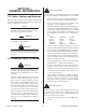
SECTION 1: GENERAL INFORMATION 1.01 Notes, Cautions and Warnings GASES AND FUMES Gases and fumes produced during the plasma cutting process can be dangerous and hazardous to your health. • Keep all fumes and gases from the breathing area. Keep your head out of the welding fume plume. Throughout this manual, notes, cautions, and warnings are used to highlight important information.
• Wear dry gloves and clothing. Insulate yourself from the work piece or other parts of the welding circuit. • Repair or replace all worn or damaged parts. • Extra care must be taken when the workplace is moist or damp. • Install and maintain equipment according to NEC code, refer to item 9 in Subsection 1.03, Publications. PLASMA ARC RAYS Plasma Arc Rays can injure your eyes and burn your skin. The plasma arc process produces very bright ultra violet and infra red light.
6. ANSI Standard Z49.2, FIRE PREVENTION IN THE USE OF CUTTING AND WELDING PROCESSES, obtainable from American National Standards Institute, 1430 Broadway, New York, NY 10018 ATTENTION Toute procédure pouvant résulter l’endommagement du matériel en cas de nonrespect de la procédure en question. 7. AWS Standard A6.0, WELDING AND CUTTING CONTAINERS WHICH HAVE HELD COMBUSTIBLES, obtainable from American Welding Society, 550 N.W. LeJeune Rd, Miami, FL 33126 AVERTISSEMENT 8.
• Eloignez toute fumée et gaz de votre zone de respiration. Gardez votre tête hors de la plume de fumée provenant du chalumeau. • Utilisez un appareil respiratoire à alimentation en air si l’aération fournie ne permet pas d’éliminer la fumée et les gaz. • Les sortes de gaz et de fumée provenant de l’arc de plasma dépendent du genre de métal utilisé, des revêtements se trouvant sur le métal et des différents procédés.
ultra-violets très forts. Ces rayons d’arc nuiront à vos yeux et brûleront votre peau si vous ne vous protégez pas correctement. • Pour protéger vos yeux, portez toujours un casque ou un écran de soudeur. Portez toujours des lunettes de sécurité munies de parois latérales ou des lunettes de protection ou une autre sorte de protection oculaire. • Portez des gants de soudeur et un vêtement protecteur approprié pour protéger votre peau contre les étincelles et les rayons de l’arc.
9. Norme 70 de la NFPA, CODE ELECTRIQUE NATIONAL, disponible auprès de la National Fire Protection Association, Batterymarch Park, Quincy, MA 02269 10. Norme 51B de la NFPA, LES PROCÉDÉS DE COUPE ET DE SOUDAGE, disponible auprès de la National Fire Protection Association, Batterymarch Park, Quincy, MA 02269 11.
1.07 Declaration of Conformity Manufacturer: Thermal Dynamics Corporation Address: 82 Benning Street West Lebanon, New Hampshire 03784 USA The equipment described in this manual conforms to all applicable aspects and regulations of the ‘Low Voltage Directive’ (European Council Directive 73/23/EEC as amended by Council Directive 93/68/EEC) and to the National legislation for the enforcement of this Directive.
1.08 Statement of Warranty LIMITED WARRANTY: Thermal Dynamics® Corporation (hereinafter “Thermal”) warrants that its products will be free of defects in workmanship or material.
SECTION 2: INTRODUCTION & DESCRIPTION 2.1 SYSTEM DESCRIPTION PAK 15XC Power Supply Work Cable Torch Leads Remote Control Panel A-00875 PCM-150 Machine Torch Spare Parts Kit Figure 2-A The Merlin PAK 15XC Plasma Arc Cutting/Gouging System The Merlin PAK 15XC System Includes: • PAK 15XC 150 Amp Power Supply with Running Gear and Handle • PCH-150 90° or 70° Hand Torch (or) PCM-150 Machine Torch with Mounting Assembly • 25 ft (7.6 m) or 50 ft (15.2 m) Torch Leads • PCH/M-150 Spare Parts Kit • 25 ft (7.
2.2 POWER SUPPLY SPECIFICATIONS Input Power Voltage Frequency Phase Amperage 200/220/230 380/415/460 500/575 50 or 60 Hz 50 or 60 Hz 50 or 60 Hz 3 3 3 84/76/73 44/40/36 34/29 Table 3-A, Section 3.4 contains information on power input, current ratings, circuit protection, and wire sizes. Output Power Duty Cycle Shipping Weight Continuously adjustable from 50 to 150 amps 100% duty cycle. Approximate Shipping Weight - 678 lbs (308 kg) Enclosure Only: A-00876 38.38 in (0.98 m) 24.12 in (0.
2.3 TORCH SPECIFICATIONS Torch Configurations • PCH-150 90° Hand Torch • PCH-150 70° Hand Torch • PCM-150 Machine Torch Torch Leads Lengths Standard lengths of 25 ft (7.6 m) or 50 ft (15.2 m). Extendable in increments of 25 ft or 50 ft up to a maximum of 150 ft (45.7 m) with available leads extension packages (see Section 2.
2.3 TORCH SPECIFICATIONS (continued) PCH-150 90o Hand Torch 13.31 in (338 mm) 3.81 in (97 mm) 1.62 in (41 mm) PCH-150 70o Hand Torch 13.87 in (352 mm) 3.96 in (101 mm) 1.62 in (41 mm) PCM-150 Machine Torch With Rack And Pinion Mounting Assembly 6.75 in (171 mm) Min. 16.75 in (425 mm) Max. 1.62 in (41 mm) 1.38 in (35 mm) 17.
2.4 OPTIONS AND ACCESSORIES Power Supply Options and Accessories • Remote Control Panel - For machine torch systems, the low profile operator control panel allows system control from a remote location with 25 or 50 ft (7.6 or 15.2 m) cable included. • Remote Pendant Control - Hand-held remote contactor control device for machine torch systems. • Computer Control Cable Kits - For interfacing the power supply with a computer or auxiliary control device. Available in 5 or 10 ft (1.5 or 3.0 m) lengths.
2.5 THEORY OF OPERATION Plasma Arc Cutting and Gouging Plasma is a gas which is heated to an extremely high temperature and ionized so that it becomes electrically conductive. The plasma arc cutting process uses this plasma to transfer an electric arc to a workpiece. The metal to be cut is melted by the intense heat of the arc and then blown away. The Merlin PAK 15XC is a high performance plasma cutting system designed to cut most metals up to two inches thick.
2.5 THEORY OF OPERATION (continued) Plasma Gas Flow (continued) Secondary Flow The torch also uses a secondary gas (or water) which assists the high velocity plasma gas in blowing molten metal from the area of the cut to create a fast, slag-free cut. The secondary flow (Zone C, Figure 2-D) also cools the torch and minimizes heat input to the workpiece.
2.5 THEORY OF OPERATION (continued) Interlocks Parts-In-Place Interlock The system has several built-in interlocks to provide safe and efficient operation. When an interlock shuts down the system, the torch switch (or control device) must be used to restart the system. The torch has a built-in parts-in-place interlock that prevents accidental torch starting when torch parts are not properly installed. A flow switch on the coolant return lead detects reduced coolant flow caused by improper torch assembly.
SECTION 3: INSTALLATION PROCEDURES 3.1 UNPACKING THE SYSTEM The power supply is skid-mounted and protected with a carton and padding material to prevent damage during shipment. The power supply, work cable, torch, and torch leads are factory-assembled and packaged together. Also packed with the system are: • Spare parts kit for the torch • Coolant de-ionizing cartridge • Air filter assembly (for air systems) 1. Remove all packing material. 2. Locate the packing list.
3.2 LOCATION Choosing the Location Select a clean, dry location with good ventilation and adequate working space around all components. The power supply is air cooled and air flow through the front, rear, and side panels must not be obstructed. At least two feet (0.61 m) of clearance should be provided on all sides. CAUTION Operation without proper air flow will inhibit proper cooling and reduce duty cycle.
3.3 PLASMA AND SECONDARY CONNECTIONS (continued) Input Gas Connections (Air Operation) Systems that are set up for operation with shop air require installation of the air line filter on the plasma input fitting on the rear panel. These systems are shipped with the following components: (1) (2) (1) (1) (1) Air Line Filter Installation Air Line Filter Assembly (For Plasma Line) Hex Nipples 90° Female Elbow 90° Street Elbow Y-Hose Assembly Refer to Figure 2-B and: 1.
3.3 PLASMA AND SECONDARY CONNECTIONS (continued) Air Line Filter Installation (continued) 5. Connect one side of the Y-hose assembly into the other side of the 90° street elbow. 6. Thread the 90° female elbow onto the other end of the second hex nipple. Fasten both sides securely. 7. Connect the other side of the Y-hose assembly to the fitting on the rear panel marked SECONDARY. 8. Connect the supply line from the source to the Y-hose assembly. The supply hose must be 3/8 in (10 mm) min.
3.3 PLASMA AND SECONDARY CONNECTIONS (continued) Secondary Water Connections 1. The water source must be capable of delivering a minimum water pressure of 50 psi (3.5 bar) and flow of 8 gph (30.3 lph). 2. Connect the secondary water supply hose to the rear panel fitting marked SEC. WATER. The water source does not need to be deionized, but in water systems with extremely high mineral content a water softener is recommended.
3.4 ELECTRICAL CONNECTIONS Electrical Requirements The PAK 15XC power supply is designed to accept a variety of input voltages: • 200/220/230 VAC • 380/415/460 VAC • 500/575 VAC Electrical Connections The electrical power source must conform to local electric code and the following recommended circuit protection and wiring requirements (see Table 3-A). 1. Check the three-phase electrical power source for line voltage and proper circuit protection and wiring (see Table 3-A).
3.
3.5 WORK AND GROUND CONNECTIONS Machine torch systems are equipped with shielded torch leads to minimize RF interference from high frequency pilot arc initiation. Follow these grounding procedures when installing machine torch systems: 1. Connect the ground wire (from the front panel) to a solid earth ground, which is created by driving a copper rod approximately 7 ft (2 m) into the earth. Locate the rod as close as possible to the power supply. Cut the ground wire to the appropriate length. 2.
3.6 COOLANT INSTALLATION Coolant Installation Refer to Figure 3-F and: 1. Locate the coolant de-ionizing cartridge and remove from the plastic shipping bag. 2. Remove the plastic cover from the coolant reservoir filler. 3. Place the de-ionizing cartridge into the basket in the coolant reservoir. 4. Fill the reservoir to the line marked FULL on the rear panel. Use only Thermal Arc torch coolant.
3.7 AUXILIARY CONNECTIONS Remote Operator Control Panel Installation The Remote Operator Control Panel consists of the control panel enclosure and cables required for connection. 1. Connect the control cable to the receptacle marked REMOTE (J15) on the rear panel. 2. Connect the other end of the control cable to the receptacle marked PS (J37) on the remote operator control panel enclosure. Computer Control Interface Installation 1.
3.7 AUXILIARY CONNECTIONS (continued) POWER SUPPLY SC-5 CONTROL CONSOLE D SC-5 REMOTE CONTROL B TORCH POSITIONER (LIFTER) E A C F CNC CONTROL WORK GROUND POWER SUPPLY REMOTE CONTROL Cable Description Letter Designation SC-5 Remote to Console A SC-5 Torch Lifter (Positioner) to Console B SC-5 Console to Power Supply Remote A-00879 C/F SC-5 Console to Power Supply D SC-5 Console to Work (Ground) E NOTE - See Catalog Pages for ordering information.
3.8 LIFTING THE POWER SUPPLY WARNING Do not lift the power supply by the handles. CAUTION Do not lift a power supply equipped with a cylinder rack running gear. The recommended method for lifting the power supply is to use a forklift (see Figure 3-H). Approach from the front or rear of the unit. Place the forks between the rear wheels or the front casters. Center the forks under the unit and carefully check for proper balance before lifting.
SECTION 4: OPERATION 4.1 OPERATING CONTROLS 1 2 ON 5 4 7 6 8 9 10 RUN COOLANT 100 125 75 AC SET 50 TEMP GAS PRES. COND. DC PILOT 150 AMPS OFF PURGE A-00887 3 Figure 4-A PAK 15XC Operating Control Panel Control Indicator 1. ON/OFF Switch 2. RUN/SET/PURGE Switch 3. Current Control 4. AC Power Indicator ON position activates all system control circuits. OFF position deactivates control circuits. RUN position is used for torch operation.
4.1 OPERATING CONTROLS (continued) Figure 4-B PAK 15XC Upper Gauge Panel Control Indicator Function 1. Secondary Pressure Control Adjusts secondary gas pressure. Pull knob out and turn clockwise to increase secondary pressure to desired level. 2. Secondary Pressure Gauge Displays secondary pressure from 0 - 100 psi (0 - 6.9 bar). 3. Secondary Mode Selector Selects secondary mode to gas, oxygen (no secondary), or water. See Section 4.
4.1 OPERATING CONTROLS (continued) 3 2 1 E-STOP RUN START 7 AMPS A 4 8 6 CURRENT STOP PURGE A-00575 5 9 PIERCE DELAY CSD 4 3 2 1 0 5 6 7 8 9 10 11 SPEED A LOW HIGH 10 Figure 4-C PAK 15XC Remote Operator Control Panel (RC6045) Function Control Indicator 1. E-STOP (Emergency Stop) 2. RUN/PURGE Switch 3. START Switch 4. Start Enable Indicator 5. STOP Switch 6.
4.2 PRE-OPERATION SET-UP The pre-operation set-up procedure should be followed at the beginning of each shift: WARNING Coolant Check Torch Check Optional Auto-Restart Settings Input Power Check Disconnect primary power to the system before disassembling the torch, leads, or power supply. 1. Check the coolant level indicator and add coolant if necessary (see Section 3.6, Coolant Installation). 2. Check the torch for proper assembly (see Section 5.1, Torch Maintenance).
4.2 PRE-OPERATION SET-UP (continued) Additional Line Purge 9. If additional purging of the plasma gas line is desired, move the RUN/SET/PURGE switch to PURGE position. In PURGE mode, with secondary mode selector set to GAS, the GAS indicator will not come on because only plasma gas runs and the secondary gas flow switch is not satisfied. 10. Return the RUN/SET/PURGE switch to RUN. The system is now ready for operation. NOTE Refer to Section 3.12 for detailed block diagram of the Sequence Of Operation.
4.3 TORCH PARTS SELECTION (continued) WARNING CAUTION Disconnect primary power to the system before disassembling the torch, leads, or power supply. Do not interchange parts. Make sure both the tip and electrode in the torch correspond with the plasma gas and secondary being used. Cutting tips and electrodes can be identified by the ring(s) around the diameter (see Figure 4-E).
4.3 TORCH PARTS SELECTION (continued) Cutting Gouging Air Plasma Oxygen Plasma Air Plasma 50 Amp (.043) Tip Cat. No. 9-5748 O2 Plasma 50 Amp (.043) Tip Cat. No. 9-5753 N2 Plasma 50 Amp (.043) Tip Cat. No. 9-5765 Air Plasma 100 Amp (.055) Tip Cat. No. 9-5747 O2 Plasma 100 Amp (.057) Tip Cat. No. 9-5752 N2 Plasma 100 Amp (.052) Tip Cat. No. 9-5766 Air Plasma 150 Amp (.070) Tip Cat. No. 9-5746 O2 Plasma 150 Amp (.070) Tip Cat. No. 9-5751 N2 Plasma 150 Amp (.067) Tip Cat. No.
4.4 GAS SELECTION FOR PLASMA CUTTING • Air plasma is normally used with air secondary. AIR PLASMA • Only clean, dry air is recommended for use as plasma gas. Any oil or moisture in the air supply can substantially reduce torch parts life. • Most often used on ferrous or carbon base materials to obtain good cutting quality at faster cutting speeds. • Provides satisfactory results on non-ferrous materials. • Can be used in place of air plasma with air secondary or CO2.
4.4 GAS SELECTION FOR PLASMA CUTTING (continued) • Air secondary is normally used when operating with air plasma and occasionally with nitrogen plasma. AIR SECONDARY • Inexpensive - reduces operating costs. • Improves cut quality on some ferrous materials. • CO2 secondary is used with nitrogen or Ar/H2 plasma. CO2 SECONDARY • Provides good cut quality on ferrous or non-ferrous materials. • May reduce smoke when used with Ar/H2 plasma. • Nitrogen secondary is used with Ar/H2 plasma.
4.4 GAS SELECTION FOR PLASMA CUTTING (continued) Cut Quality Cut quality requirements differ depending on application. For instance, nitride build-up and bevel angle may be major factors when the surface that is cut will be welded after the cutting operation. Dross-free cutting is important when finish cut quality is desired to avoid a secondary cleaning operation. Cut Surface • The desired or specified condition (smooth or rough) of the face of the cut.
4.4 GAS SELECTION FOR PLASMA CUTTING (continued) Description Excellent Good Cut Characteristics: Minimum bevel (0 - 4°), minimum kerf (2 x tip orifice), little or no dross, smooth cut surface. Slight bevel (0 - 10°), slightly wider kerf (2-1/2 x tip orifice), some dross (easily removed), medium-smooth cut surface, slight top edge rounding. Fair Excessive bevel (over 10°), wide kerf (over 2-1/2 x tip orifice), medium to heavy dross, rough cut surface, top edge rounding. NR Not Recommended.
4.5 PLASMA CUTTING OPERATION WARNING Be sure the operator is equipped with proper gloves, clothing, eye and ear protection and that all precautions at the front of this manual have been followed. Make sure no part of the operator’s body comes in contact with the workpiece when the torch switch is pressed. CAUTION The sparks from the cutting process can cause damage to coated, painted or other surfaces such as glass, plastic, and metal. CAUTION Do not interchange parts.
4.5 PLASMA CUTTING OPERATION (continued) Auto-Restart Options The auto-restart function provides an immediate pilot arc restart during post-flow if the torch is brought within range of the workpiece. The power supply can be set up to provide a variety of optional auto-restart settings.
4.5 PLASMA CUTTING OPERATION (continued) Auto-Restart (continued) On/Off (SW1) Note: Either pole set to 1(on) disables auto-restart function Normal/Delayed (SW2) Note: Either pole set to 1(on) sets auto-restart function Pre-Flow Delay (SW3) Four two-pole DIP switches located on the control logic PC board control the auto-restart functions.
4.
4.6 HAND TORCH OPERATION WARNING Be sure the operator is equipped with proper gloves, clothing, eye and ear protection and that all precautions at the front of this manual have been followed. Make sure no part of the operator’s body comes in contact with the workpiece when the torch switch is pressed. CAUTION The sparks from the cutting process can cause damage to coated, painted or other surfaces such as glass, plastic, and metal. Plasma Cutting Operation (Hand Torch) Do not interchange parts.
4.6 HAND TORCH OPERATION (continued) Hand Torch Operation (continued) 2. To positively locate the line of the cut, position the torch over the workpiece, resting the front edge of the shield cup on the edge where the cut is to start. 3. Lower the welding helmet. Press and hold the torch control switch. After a two second gas purge, the pilot arc will start. The pilot arc will stay on as long as the torch control switch is held. 4.
4.7 MACHINE TORCH OPERATION Cutting with a Machine Torch 1. A machine torch should be aligned perpendicular to the surface of the workpiece to obtain a clean, vertical cut. Use a square to align the torch (see Figure 4-I). 2. Position the center of the torch over the edge of the workpiece where the cut is to start. The transferred cutting arc will then be established at the plate edge when the torch is activated. 3.
4.7 MACHINE TORCH OPERATION (continued) Cutting with a Machine Torch (continued) 5. Cut with a standoff of 1/8 - 3/8 in (3 - 10 mm) from the work. The torch should be held perpendicular to the workpiece while cutting. Start cutting slowly and adjust cutting speed for optimum cutting performance. Section 3.11, Cutting Speeds, contains typical cutting speeds for various materials and material thicknesses. A standard shield cup is recommended for most machine cutting applications.
4.7 MACHINE TORCH OPERATION (continued) Corner Slowdown (CSD) The corner slowdown feature provides an output current reduction in to correspond with the reduction in torch travel speed as a mechanized torch moves through a corner. When activated by CNC or other control device, the corner slowdown eliminates excessive metal removal in corners. Normally open (NO) contacts (supplied by the control device) close when the torch travel speed decreases through a corner.
4.8 PIERCING In some cutting operations, it may be desirable to start the cut within the plate area rather than at the plate edge. Piercing the plate is not recommended on plates having a thickness greater than 3/4 in (19 mm). Blowback from the piercing operation can shorten the life of torch parts. All piercing should therefore be done as quickly as possible and at maximum amperage (150 amps) and maximum standoff.
4.9 GOUGING OPERATION WARNING Be sure the operator is equipped with proper gloves, clothing, eye and ear protection and that all precautions at the front of this manual have been followed. Make sure no part of the operator’s body comes in contact with the workpiece when the torch switch is pressed. CAUTION The sparks from the gouging process can cause damage to coated, painted or other surfaces such as glass, plastic, and metal. CAUTION Do not interchange parts.
4.9 GOUGING OPERATION (continued) Gouging Parameters Gouging performance depends on the torch travel speed, the current level, the angle at which the torch is held to the workpiece (lead angle), and the distance between the torch tip and the workpiece (standoff). Gouging can be accomplished with either a hand or machine torch. Torch Travel Speed Optimum torch travel speed for gouging is between 20 and 120 inches per minute (0.5 and 3.0 meters per minute).
4.9 GOUGING OPERATION (continued) Standoff Distance Slag Build-up The tip to work distance affects gouge quality and depth. A standoff of 1/8 - 1/4 in (3 - 6 mm) allows smooth, consistent material removal. A smaller standoff may result double arcing from tip to work. A standoff greater than 1/4 in (6 mm) may result in minimal metal removal or loss of transferred main arc.
4.10 COMMON OPERATING ERRORS Listed below are common cutting problems followed by probable causes of each. If the problems are caused by a power supply problem, refer to Section 5.11, Troubleshooting Guide). Insufficient Penetration a. Cutting speed too high b. Current too low c. Metal too thick d. Worn or damaged torch parts Main Arc Extinguishes a. Cutting speed too low b. Standoff too high Dross Formation a. Improper gas pressure b. Improper cutting speed (See Section 3.11, Cutting Speeds) c.
4.11 CUTTING SPEEDS This Section contains information on cutting speeds for hand and automated applications with PCH/M-150 Torch. The information is organized into two subsections as follows: A. Hand Cutting Speeds B. Automated Cutting Speeds Each subsection contains cutting speed charts for various plasma and secondary combinations on different materials.
A. Hand Cutting Speeds Material Thickness Inches per Minute (Meters per Minute) 50 Amps 100 Amps 150 Amps 90 (2.29) 150 (3.81) 1/2 48 (1.22) 80 (2.30) 3/4 30 (0.76) 40 (1.02) 1 17 (0.43) 25 (0.64) 1-1/4 10 (0.25) 18 (0.46) 1/8 150 (3.81) 3/16 110 (2.79) 1/4 65 (1.65) 1-1/2 14 (0.36) 2 6 (0.15) Table 4-E Cutting Speeds - Air Plasma on Mild Steel Gage MM Inches 2.00 50 45 A-00881 1.
Hand Cutting Speeds (continued) Material Thickness Inches per Minute (Meters per Minute) 50 Amps 100 Amps 130 (3.30) 225 (5.7) 1/4 65 (1.65) 100 (2.54) 3/8 28 (.71) 1/2 16 (.41) 1/8 150 Amps 3/16 160 (4.06) 100 (2.54) 58 (1.47) 80 (2.03) 3/4 32 (0.81) 35 (0.89) 1 22 (0.56) 28 (0.71) 1-1/2 12 (0.30) 2 5 (0.13) Table 4-F Cutting Speeds - Oxygen Plasma on Mild Steel, CO2 Secondary Gage MM Inches 2.00 50 45 A-00883 1.
Hand Cutting Speeds (continued) Material Thickness Inches per Minute (Meters per Minute) 50 Amps 1/8 100 (2.54) 1/4 40 (1.02) 5/16 30 (0.76) 3/8 9 (0.23) 1/2 100 Amps 150 Amps 140 (3.56) 175 (4.45) 75 (1.90) 110 (2.79) 60 (1.52) 85 (2.16) 3/4 40 (1.02) 1 25 (0.64) 1-1/2 12 (0.30) 2 Table 4-G Cutting Speeds - Nitrogen Plasma on Stainless Steel Gage MM Inches 2.00 50 45 A-00882 1.
Hand Cutting Speeds (continued) Material Thickness Inches per Minute (Meters per Minute) 50 Amps 100 Amps 150 Amps 1/8 1/4 5/16 3/8 1/2 35 (0.89) 3/4 27 (0.69) 1 20 (0.51) 1-1/2 10 (0.25) 2 Table 4-H Cutting Speeds - Argon/Hydrogen Plasma on Stainless Steel Gage MM Inches 2.00 50 45 A-00886 1.75 Optimum Cutting Speeds Ar/H2 Plasma - N2 Secondary on Stainless Steel 150 Amps MATERIAL THICKNESS 40 1.50 35 30 25 20 1.25 1.00 .75 15 .50 10 .
Hand Cutting Speeds (continued) Material Thickness Inches per Minute (Meters per Minute) 50 Amps 100 Amps 150 Amps 1/8 150 (3.81) 225 (5.72) 275 (6.99) 1/4 40 (1.02) 135 (3.43) 150 (3.81) 1/2 60 (1.52) 95 (2.41) 3/4 18 (0.46) 52 (1.32) 1 15 (0.38) 36 (0.91) 5/16 3/8 1-1/2 18 (.46) 2 Table 4-I Cutting Speeds - Air Plasma on Aluminum Gage MM Inches 2.00 50 45 A-00884 1.75 Optimum Cutting Speeds Air Plasma - Air Secondary on Aluminum 150 Amps 100 Amps MATERIAL THICKNESS 40 1.
Hand Cutting Speeds (continued) Material Thickness Inches per Minute (Meters per Minute) 50 Amps 100 Amps 150 Amps 1/8 1/4 100 (2.54) 5/16 3/8 1/2 75 (1.90) 3/4 60 (1.52) 1 35 (0.89) 1-1/2 21 (0.53) 2 Table 4-J Cutting Speeds - ArH2 Plasma/Nitrogen Secondary on Aluminum Gage MM Inches 2.00 50 45 A-00885 1.75 Optimum Cutting Speeds ArH2 Plasma - N2 Secondary on Aluminum 150 Amps 100 Amps MATERIAL THICKNESS 40 1.50 35 30 1.25 25 1.00 20 .75 50 Amps 15 .50 10 .
B. Automated Cutting Speeds Mild Steel PCM-150 Torch Head Electrode Tip Shield Cup Air Plasma / Air Secondary General purpose cutting Plasma @ 60 psi (4.1 bar) A-03448 Secondary @ 60 psi (4.1 bar) Material Thickness Tip Electrode Output Volts Amperage Speed (Per Minute) Standoff Pierce Height Pierce Kerf Width inches mm Cat # Cat # vdc Amps inches meters inches mm inches mm Delay (Sec) inches mm 16 ga 1.5 9-5747 9-5749 100 80 300 7.62 0.125 3.2 0.187 4.7 0.1 0.
Automated Cutting Speeds (continued) PCM-150 Torch Head Stainless Steel Electrode Tip Shield Cup Air Plasma / Air Secondary General purpose cutting A-03448 Plasma @ 60 psi (4.1 bar) Secondary @ 60 psi (4.1 bar) Material Thickness Tip Electrode Output Volts Amperage Speed (Per Minute) Standoff Pierce Height Pierce Kerf Width inches mm Cat # Cat # vdc Amps inches meters inches mm inches mm Delay (Sec) inches mm 16 ga 1.5 9-5747 9-5749 100 80 300 7.62 0.125 3.2 0.187 4.
Automated Cutting Speeds (continued) PCM-150 Torch Head Stainless Steel Electrode Tip Shield Cup A-03448 Argon-Hydrogen Plasma / Nitrogen Secondary Heavy duty, extended electrode life, extra square, oxide free, reduced smoke Plasma @ 60 psi (4.1 bar) Secondary @ 60 psi (4.
Automated Cutting Speeds (continued) PCM-150 Torch Head Aluminum Electrode Tip Shield Cup Air Plasma / Air Secondary General purpose cutting A-03448 Plasma @ 60 psi (4.1 bar) Secondary @ 60 psi (4.1 bar) Material Thickness Tip Electrode Output Volts Amperage Speed (Per Minute) Standoff Pierce Height Pierce Kerf Width inches mm Cat # Cat # vdc Amps inches meters inches mm inches mm Delay (Sec) inches mm 16 ga 1.3 9-5747 9-5749 100 80 300 7.62 0.125 3.2 0.187 4.7 0.
Automated Cutting Speeds (continued) PCM-150 Torch Head Aluminum Electrode Tip Shield Cup A-03448 Argon-Hydrogen Plasma / Nitrogen Secondary Heavy duty, extended electrode life, extra square, oxide free, reduced smoke Plasma @ 60 psi (4.1 bar) Secondary @ 60 psi (4.1 bar) Material Thickness Tip Electrode Output Volts Amperage Speed (Per Minute) Standoff Pierce Height Pierce Kerf Width inches mm Cat # Cat # vdc Amps inches meters inches mm inches mm Delay (Sec) inches 3/8 9.
4.
SECTION 5: CUSTOMER/OPERATOR SERVICE 5.1 TORCH MAINTENANCE Disconnect primary power to the system before disassembling the torch, leads, or power supply. WARNING Refer to Figure 5-A and: Routine Inspection and Replacement of Consumable Parts: 1. Remove the shield cup (1) from the torch body (6 or 7). 2. Unscrew the tip (2) using the tip wrench (9). Check for tip wear (indicated by elongated or oversize orifice). Clean the tip and make sure the threads and sealing face are not damaged.
5.1 TORCH MAINTENANCE (continued) NOTE If face of electrode is pitted or gouged more than 3/32 in (2.4 mm) deep, the electrode should be replaced (see Figure 5-B). 4. Replace the electrode in the torch body. Secure in place using the electrode wrench. 5. Replace the tip in the front of the torch and secure it with the tip wrench. CAUTION Do not overtighten the electrode or tip. 6. Inspect the shield cup for damage. Wipe it clean, or replace if it appears to be damaged. 7. Re-install the shield cup.
5.2 HAND TORCH HEAD REPLACEMENT (continued) Hand Torch Head Replacement (continued) 4. With a twisting motion, pull the handle from the torch head. Slide the handle back over the leads to expose the leads connections. 5. Remove the tape that secures the lead connections around the insulating tab. Disconnect the plasma, secondary, coolant supply, and coolant return leads from the torch head.
5.3 MACHINE TORCH HEAD REPLACEMENT WARNING Machine Torch Leads Replacement Disconnect primary power to the system before disassembling the torch, leads, or power supply. Refer to Figure 5-D and: 1. Remove the electrical tape from the end of the nylon outer leads sleeving next to the mounting assembly and push the sleeving back onto the leads approximately one foot (0.3 m) to expose the shielded inner leads sleeving. 2.
5.3 MACHINE TORCH HEAD REPLACEMENT (continued) CAUTION Make sure the insulating tab completely separates the coolant supply lead (negative) from the plasma, secondary, and coolant return leads. 7. Replace the mounting assembly onto the torch head. 8. Secure the shielded inner sleeving to the leads with electrical tape. Position the end of the sleeving a few inches back from the mounting assembly. 9. Position the nylon outer sleeving over the shielded inner sleeving.
5.4 HAND TORCH SWITCH REPLACEMENT WARNING Hand Torch Head Replacement Disconnect primary power to the system before disassembling the torch, leads, or power supply. Refer to Figure 5-C and: 1. Roll the sheath up over the torch handle to expose the torch switch connectors and the torch switch. 2. Remove the tape from the two single-pin torch switch connectors and disconnect the torch switch leads. 3. Replace the torch switch and connect the two torch switch leads connectors. 4.
5.5 HAND TORCH LEADS REPLACEMENT WARNING Hand Torch Leads Replacement Disconnect primary power to the system before disassembling the torch, leads, or power supply. Refer to Figure 5-C and: 1. Roll the torch switch sheath up over the handle to expose the two torch switch connectors. 2. Remove the tape from the end of the leads sleeving and pull the sleeving back approximately one foot (0.3 m). 3. Remove the tape from the two single-pin torch switch connectors and disconnect the torch switch leads. 4.
5.5 HAND TORCH LEADS REPLACEMENT (continued) NOTE To minimize coolant leaks during torch head replacement, perform the operation with the torch head above the level of the coolant reservoir. 6. Position the replacement leads and connect the plasma, secondary, coolant supply, and coolant return leads onto the torch head fittings. 7. Use electrical tape to secure the leads in place on the insulating tab. Locate the tape over the ferrule on the negative lead.
5.6 MACHINE TORCH LEADS REPLACEMENT WARNING Machine Torch Leads Replacement Disconnect primary power to the system before disassembling the torch, leads, or power supply. Refer to Figure 5-D and: 1. Remove the electrical tape from the end of the nylon outer leads sleeving next to the mounting assembly. 2. Push the nylon outer sleeving back up the leads approximately one foot (0.3 m) to expose the shielded inner leads sleeving. 3.
5.6 MACHINE TORCH LEADS REPLACEMENT (continued) Machine Torch Leads Replacement (continued) 10. Position the nylon outer sleeving over the shielded inner sleeving. The shielded inner sleeving must be completely covered by the outer sleeving to avoid any possible contact with the mounting assembly. 11. Secure the nylon outer leads sleeving to the leads with electrical tape. Position the tape close to the back of the mounting assembly. Power Supply Connections Refer to Figure 5-E and: 12.
5.7 LEADS EXTENSION KITS - HAND TORCH Leads extension packages are available in 25 ft (7.6 m) or 50 ft (15.2 m) lengths. Leads can be extended up to a maximum of 150 ft (45.8 m). Leads extension kits for hand torch systems include: • Plasma, Secondary, Coolant Supply and Coolant Return Leads Extensions in 25 or 50 ft (7.6 or 15.2 m) lengths • Control Cable Extension - 25 or 50 ft (7.6 or 15.2 m) • Nylon Outer Sleeving - 25 or 50 ft (7.6 or 15.
5.7 LEADS EXTENSION KITS - HAND TORCH (continued) 7. Thread the coolant supply insulator on the leads extension into the union fitting and tighten securely. 8. Slide the plasma insulator over the plasma lead on the existing torch leads. 9. Push the plasma lead on the existing leads into the union fitting as far as possible. Connect Plasma Lead to Extension Package 10. Connect the plasma lead from the torch leads, through the union, to the plasma lead from the extension kit and tighten securely. 11.
5.8 LEADS EXTENSION KITS - MACHINE TORCH Leads extension packages are available in 25 ft (7.6 m) or 50 ft (15.2 m) lengths. Leads can be extended up to a maximum of 150 ft (45.8 m). Leads extension kits for machine torch systems include: • Plasma, Secondary, Coolant Supply and Coolant Return Leads Extensions in 25 or 50 ft (7.6 or 15.2 m) lengths • Shielded Inner Sleeving - 25 or 50 ft (7.6 or 15.2 m) • Nylon Outer Sleeving - 25 or 50 ft (7.6 or 15.2 m) • Shielded Inner Sleeving Connector - 12 in (0.
5.8 LEADS EXTENSION KITS - MACHINE TORCH (continued) Connect Existing Leads to Leads Extension Refer to Figure 5-G and: 5. Slide the 24-inch nylon outer sleeving connector over the existing leads before making connections. The connector will later be pulled down to cover all connections. 6. Remove the shrink-on tubing and tape that secures the end of the nylon outer sleeving to the existing leads. 7. At the end of the existing leads, all four individual leads are enclosed by the shielded inner sleeving.
5.8 LEADS EXTENSION KITS - MACHINE TORCH (continued) 19. Thread the plasma insulator on the leads extension into the union fitting and tighten securely. Refer to Figure 5-G and: 20. Pull each end of the shielded inner sleeving (from the existing leads and from the leads extension) up and over the plasma and coolant supply insulators. Position the 12-inch shielded inner sleeving connector down over the completed coolant supply and plasma connections.
5.9 POWER SUPPLY MAINTENANCE Fan Motor and Pump Lubrication The fan motor and pump in the power supply should be oiled twice per year or once for each 100 hours of operation. To oil the motor, remove one side panel and add two or three drops of 20 SAE oil to the front and rear oil holes on the motor. NOTE Some units may utilize a sealed motor design which does not require lubrication.
5.10 TROUBLESHOOTING THEORY Input Voltage Selection The main transformer (T1) has buss bar connections to select one of three input voltage ranges (see page 2-6). Each main transformer secondary has two taps. One secondary tap is automatically selected by the voltage selection PC board when primary power is applied. If input voltage is within the lower half of the selected voltage range (for example, 380V or 415V in the 380/415/ 460V range), the higher voltage taps are selected.
5.10 TROUBLESHOOTING THEORY (continued) Switching Control Board (continued) Logic Board Functions passes the E-Stop function of the remote. The switching control PC board also routes the shunt amp output to the digital ammeter in the remote. CSR (current greater than 25A) and over-current shutdown (greater than 175A) signals are sent to the logic PC board. The logic PC board controls the timing and sequencing of the system.
5.
5.
5.11 TROUBLESHOOTING GUIDE SYMPTOM A. No front panel LED indicators lit. Fan and pump off. POSSIBLE CAUSE 1. No primary power. See also Symptoms C and D 1. Check for proper threephase power at input terminal board 2. Blown fuse (F2) 2. Check and replace fuse if necessary 3. Disconnect primary power. Check each section for continuity. Replace switch if necessary 4. See Sction 5.12-Test A and replace board if necessary 3. Faulty ON/OFF switch (SW1) 4. Faulty voltage selection board B. AC indicator on.
5.11 TROUBLESHOOTING GUIDE (continued) SYMPTOM POSSIBLE CAUSE C. Fuse blown at disconnect when primary power is connected 1. Voltage selection bus bars connected incorrectly 1. Check and correct if necessary. 2. One leg of three-phase primary connected to chassis ground 2. Rewire input cable (see Section 3.4, Electrical Connections) 3. Main transformer shorted 3. Replace main transformer 1. Shorted input diode (D1-D6) 1. See Section 5.12-Test D and replace diode if necessary 2.
5.11 TROUBLESHOOTING GUIDE (continued) SYMPTOM F. No GAS indicator (continued) POSSIBLE CAUSE 3. Faulty pressure switch (PS1 or PS2) 3. Jump switches one at a time and check for indicator to determine which has failed. Replace switch if necessary 4. Faulty logic board 4. See Section 5.12-Test F and replace board if necessary 5. Faulty LED/current control board G. GAS indicator off, plasma and/or secondary gas does not flow Manual 0-2251 REMEDY 5. See Section 5.
5.11 TROUBLESHOOTING GUIDE (continued) SYMPTOM H. COOLANT indicator off POSSIBLE CAUSE 1. Little or no pressure shown on gauge REMEDY 1a.Check coolant level 1b. Check motor rotation and rpm. 1c. Check and replace pump if necessary I. Coolant conductivity indicator off J. DC indicator not lit (after pre-flow), no main contactor closure K. DC indicator not lit (after pre-flow), main contactor comes on momentarily. No pilot, no main arc transfer CUSTOMER/OPERATOR SERVICE 2. Clogged torch or leads 2.
5.11 TROUBLESHOOTING GUIDE (continued) SYMPTOM POSSIBLE CAUSE L. No pilot arc. DC indicator on, PCR not energized 1. Faulty logic board, switching board, or shunt amp board M. No pilot. PILOT indicator on, PCR energized, little or no spark at spark gap points 1. Faulty PSR relay N. Weak or sputtering pilot. HF stays on during pilot O. No pilot. PILOT indicator on, strong spark visible at spark gap points Manual 0-2251 REMEDY 1. See Section 5.12-Test L 1.
5.11 TROUBLESHOOTING GUIDE (continued) SYMPTOM POSSIBLE CAUSE REMEDY P. Pilot arc on, no main arc transfer (torch brought within range of work) 1. Work cable not connected 1. Connect work cable securely 2. Defective current control pot (on front panel or remote) 2. If remote is in use, disconnect J15 and set current at front panel. If transfer is okay, replace remote. If remote is not in use, see Section 5.12-Test M Q.
5.12 SERVICE AND TEST PROCEDURES The following tests are suggested for specific problems listed in the troubleshooting guide. The letter designations correspond to those listed in the “Remedy” column of the troubleshooting section. WARNING A. Voltage Selection PC Board Check 28 VAC Test Several of these tests involve voltage measurements that must be made with power on. Use extreme care when making these tests. Tests requiring voltage measurements are marked with the warning symbol.
5.12 SERVICE AND TEST PROCEDURES (continued) 1. Check the voltage input from F2 (wire #10) to J6-9 for 100 - 120 VAC. Check the input from F2 to J6-10 for 120 - 140 VAC. 120 VAC Test 2. If the voltage input is present, check the red LED indicator (D18) on the voltage selection board. If the indicator is lit, measure voltage output between F2 (wire #10) and J6-7. If the indicator is not lit, measure between F2 and J6-12. The voltage output at either point should measure 110 - 130 VAC. 3.
5.12 SERVICE AND TEST PROCEDURES (continued) C. Motor Control Contactor Check (MC1 or MC2) 120 VAC is supplied to the motor control contactors (MC1 and MC2) from the voltage selection PC board, which selects the proper tap on the main transformer (T1).
5.12 SERVICE AND TEST PROCEDURES (continued) D. Diode Check (continued) If a diode fails, check the potential causes of diode failure to make sure the replacement diode will not also fail when it is installed: 1. Isolate and check each diode separately to determine which individual diode has failed. 2. High frequency protection for the input rectifier diodes (D1-6) is provided by capacitors C1 - C6 and MOV 1-3, which are located between each side of the diode heatsink on the input filter PC board.
5.12 SERVICE AND TEST PROCEDURES (continued) F. Pressure Sensing Circuit (continued) 2. If the voltage at J1-7 is less than 1V, check the voltage at J3-3. If the voltage at J3-3 is greater than 12 vdc, replace the logic board. If the voltage at J3-3 is less than 12 vdc, replace the LED board. G. Gas Solenoid Circuits 1. Set the RUN/SET/PURGE switch to SET position. Measure continuity between the center terminal of the switch (wire #62) and each outer terminal (wires #61 and 63).
5.12 SERVICE AND TEST PROCEDURES (continued) J. Main Contactor Circuit (W1 and W2) Only one of the two main contactors (W1 and W2) is used at any given time. The K5 relay on the voltage selection PC board selects which contactor is activated. If the red LED indicator (D18) on the voltage selection board is lit, W2 is selected. If D18 is not lit, W1 is selected. There are three ways to initiate main contactor closure. Two are through the remote jack (J15).
5.12 SERVICE AND TEST PROCEDURES (continued) J. Main Contactor Circuit (continued) 1. If the start LED (D57) does not light, use the negative voltmeter probe on the logic board common (TP1) or one of the J1 common pins, check the active ‘start’ input (J1-21 for momentary start, J1-19 for maintained start from CNC or remote pendant or J1-15 from hand torch) for at or near 0 vdc (check the momentary with the switch held closed). When not activated, the ‘start’ input should measure +12 - 15 vdc.
5.12 SERVICE AND TEST PROCEDURES (continued) K. Switching Transistor Check (continued) The PWM compares shunt amp output on J9-5 with the current control signal (3.3 - 10 vdc) from the remote (J7-18) or the panel control (J10-15). A faulty shunt amp could cause the output, normally 0 vdc with no cutting arc, to go higher, shutting off the PWM and thus producing no DC.
5.12 SERVICE AND TEST PROCEDURES (continued) M. Current Control Check Manual 0-2251 The current control pot receives its high (10 V) on J10-17 and its low (3.3 V) on J10-13. The wiper (J10-15) must be 3.3 - 10 vdc. Measure the wiper between J10-15 and TP1 (ground) on the switching control board. If the high and low are present and the wiper is less than 3.3 vdc, either the control pot on the LED PC board or the ribbon cable is faulty.
CUSTOMER/OPERATOR SERVICE 5-36 Manual 0-2251
SECTION 6: PARTS LISTS 6.1 ABOUT THE PARTS LIST Parts List Contents Section 6.2 Section 6.3 Section 6.4 Section 6.5 Section 6.6 Section 6.7 Section 6.8 Section 6.9 Section 6.
6.2 SYSTEM COMPONENTS AND ACCESSORIES Item Qty. Catalog No. Number 1 2 3 4 5 6 7 8 9 10 11 12 13 14 15 16 17 1 3-2752 1 1 2-2980 2-2981 1 1 2-2982 2-2983 1 1 1 1 2-2978 2-2979 9-4380 8-3300 1 1 2 1 2 1 1 1 8-3301 8-3303 8-3302 8-3304 8-2172 7-3139 9-1021 9-1022 1 1 1 1 1 1 1 1 9-2722 9-2759 9-3053 9-4379 8-6118 3-2766 7-3460 9-4393 Description PAK 15XC Power Supply With Running Gear and Work Cable Torch and Leads Assembly PCM-150 180° Machine Torch With Pinion Assembly 25 ft (7.
4 7 8 5 6 1 3 15 2 16 9 11 10 13 17 12 14 A-00966 Manual 0-2251 6-3 PARTS LISTS
6.3 ACCESS PANEL COMPONENTS Item Qty. Catalog No.
6.4 FRONT PANEL/CHASSIS COMPONENTS Item Qty. Catalog No.
6.5 REAR PANEL COMPONENTS Item Qty. Catalog No. Number 1 2 3 4 5 6 7 8 9 10 11 12 13 14 15 16 17 18 19 20 21 22 23 24 25 26 27 28 29 30 31 PARTS LISTS 1 1 2 1 1 2 1 1 4 1 1 3 1 1 1 2 1 3 1 4 3 1 1 1 1 1 1 3 1 1 1 8-5574 8-6312 8-5143 8-1373 9-3210 8-6308 9-5545 8-5144 9-5333 8-5576 8-4274 8-0346 8-4410 8-3312 8-4275 8-5575 8-5142 8-0262 8-1787 8-0354 8-1196 9-1412 8-5141 8-0319 8-6203 8-6202 8-4276 9-4078 8-4249 9-3290 8-0232 Description Reference Designator Rear Panel Fan Assembly - 16 in.
17 14 23 13 24 22 16 25 26 18 18 21 19 20 18 20 15 27 21 20 20 12 28 11 10 6 30 8 9 5 7 31 4 3 3 29 2 1 A-00969 Manual 0-2251 6-7 PARTS LISTS
6.6 BASE COMPONENTS Item Qty. Catalog No.
20 21 10 12 9 8 20 25 13 14 11 26 23 15 21 24 22 16 17 18 19 3 7 9 4 1 5 2 6 A-00894 Manual 0-2251 6-9 PARTS LISTS
6.7 UPPER CHASSIS COMPONENTS Item Qty. Catalog No.
20 7 18 8 19 28 17 16 15 13 14 25 24 11 9 10 30 7 12 33 44 21 22 33 22 29 9 36 30 5 31 32 33 22 33 10 27 6 34 27 28 1 41 37 40 39 35 38 42 41 25 26 23 4 3 2 43 24 30 A-00970 Manual 0-2251 6-11 PARTS LISTS
6.8 MAIN HEATSINK COMPONENTS Item Qty. Catalog No.
20 27 11 14 19 11 31 16 13 10 15 11 30 28 21 18 18 31 31 22 17 9 12 31 17 6 9 31 23 2 31 2 26 17 11 31 24 2 5 25 2 33 3 1 (J1) 7 8 32 4 29 Art # A-06054 Manual 0-2251 6-13 PARTS LISTS
6.9 TORCH COMPONENTS Item Qty. Catalog No. Number Description 1 1 1 1 1 1 2-2380 2-2381 2-2382 9-5745 9-5743 9-5744 PCH-150 70° Hand Torch with Air Parts PCH-150 90° Hand Torch with Air Parts PCM-150 180° Machine Torch with Air Parts PCM-150 Basic 180° Machine Torch Head (No Parts) PCH-150 Basic 70° Hand Torch Head (No Parts) PCH-150 Basic 90° Hand Torch Head (No Parts) 3 4 5 2 1 1 8-5570 8-0540 8-0537 O-Ring (Handle) O-Ring (Shield Cup, Lg.) O-Ring (Shield Cup, Sm.
14 9 1 10 6 11 7 2 4 15 16 5 12 8 13 17 3 18 19 21 20 A-00972 Manual 0-2251 6-15 PARTS LISTS
6.10 TORCH ACCESSORIES Item Qty. Catalog No. Number Description 1 2 3 1 1 1 9-1063 9-1246 9-1064 Handle Switch Assembly Switch Retaining Sheath 4 5 6 7 1 1 1 1 8-2158 7-3207 7-2827 8-4204 Adaptor Positioning Tube Pinion Assembly Bushing (End Cap) 1 8-3322 Adaptor - Torch to 2-1/4 in. Positioning Tube 1 1 1 1 4-2863 4-2864 4-2865 4-2866 PCH-150 Replacement Hand Torch Leads - 25 ft (7.6 m) PCH-150 Replacement Hand Torch Leads - 50 ft (15.2 m) PCM-150 Replacement Machine Torch Leads - 25 ft (7.
APPENDIX 1: LADDER DIAGRAM - 120 VAC T1 F2 SW1-A 10 NEON IND1 9 E-STOP 8 5A, 250 VAC K1 AC 15 VOLTAGE SELECTION BOARD 14 K4 (HV) K3 (LV) 3 K3 (LV) SWITCHING CONTROL BOARD (Energized if remote cable is not installed) MC1 K4 (HV) 4 MC2 110 LOGIC BOARD K5 (LV) 24 21 K2 23 W1 K5 (HV) 22 W2 SOL1 - PLASMA GAS K4 50 SECONDARY SELECTION SWITCH SW3-A K3 75 SOL2 - SECONDARY GAS 88 SEC 02 N/C SOL3 - SECONDARY WATER 89 PCR K5 5 T3 HIGH FREQ PSR 94 24 110 HFWS K1-A 93 A-00877 Manual 0-
APPENDIX 2: LADDER DIAGRAM - 15 VDC LOGIC CONTROL BOARD SW2 PLASMA 13 GAS CONTROL CIRCUIT K4 RUN SET 12 PURGE 11 START/STOP (CNC) SECONDARY PRE-FLOW & POST-FLOW CIRCUIT K3 19 18 START/STOP (Hand) 14 15 D57 START (Momentary CNC/Remote) SWITCH RECOGNITION START INDICATOR 21 20 STOP (Momentary CNC/Remote) 17 16 FS1 W CONTACTOR K2 5 CONTACTOR CONTROL 4 TS3 TS1 TS2 9 D38 PWM ENABLE TP4 7 PS1 6 WATER CONTACTOR DISABLE (Only after main contactor initially closes) SENSE BRIDGE VOLT
APPENDIX 3: DIGITAL CURRENT CONTROL INTERFACE A-01579 Manual 0-2251 A-3 APPENDIX
APPENDIX 4: CNC INTERFACE A-01580 APPENDIX A-4 Manual 0-2251
APPENDIX 5: POWER SUPPLY TO REMOTE CONTROL CABLE INTERFACE A-01581 Manual 0-2251 A-5 APPENDIX
APPENDIX 6: REMOTE CONTROL CHASSIS SCHEMATIC A-01582 APPENDIX A-6 Manual 0-2251
APPENDIX 7: ROUTINE MAINTENANCE SCHEDULE This recommended schedule applies to all types of water cooled plasma cutting systems. Some systems will not have all the parts listed and those checks need not be performed. NOTE The actual frequency of maintenance may need to be adjusted according to the operating environment. Daily Operational Checks or Every Six Arc Hours: 1. Check torch parts, replace if damaged. 2. Check plasma and secondary supply and pressure/flow. 3.
APPENDIX 8: SYSTEM SCHEMATIC Art # A-05857 APPENDIX A-8 Manual 0-2251
Art # A-05857 Manual 0-2251 A-9 APPENDIX