61 S THERMAL ARC ® Inverter Arc Welder Art# A-09194_AB Operating Manual Revision: AD Issue Date: January 14, 2011 Operating Features: Manual No.
WE APPRECIATE YOUR BUSINESS! Congratulations on your new Thermal Arc product. We are proud to have you as our customer and will strive to provide you with the best service and reliability in the industry. This product is backed by our extensive warranty and world-wide service network. To locate your nearest distributor or service agency call 1-800-462-2782, or visit us on the web at www.Thermalarc.com.
! WARNINGS Read and understand this entire Manual and your employer’s safety practices before installing, operating, or servicing the equipment. While the information contained in this Manual represents the Manufacturer’s best judgment, the Manufacturer assumes no liability for its use. Operating Manual Number 0-5073 for: Thermal Arc 161 S Power Source Arc Welder Thermal Arc 161 S System with Stick Kit & Case Thermal Arc 161 S System with Stick/TIG Kit & Case Part No. W1003600 Part No.
TABLE OF CONTENTS SECTION 1:SAFETY INSTRUCTIONS AND WARNINGS................................................. 1-1 1.01 1.02 1.03 1.04 1.05 1.06 1.07 1.08 1.09 Arc Welding Hazards........................................................................................ 1-1 General Safety Information for Victor CS Regulator........................................... 1-4 Principal Safety Standards............................................................................... 1-5 Symbol Chart....................
TABLE OF CONTENTS SECTION 4:OPERATION..................................................................................... 4-1 4.01 4.02 4.03 4.04 4.05 4.06 4.07 4.08 4.09 4.10 4.11 4.12 4.13 4.14 4.15 4.16 4.17 4.18 4.19 4.20 4.21 4.22 Front Panel...................................................................................................... 4-1 Welding Current Control Explanation............................................................... 4-2 STICK (SMAW) Electrode Polarity......................
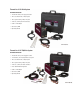
Thermal Arc 161S Stick System Part Number W1003602 • Thermal Arc 161S power supply in toolbox • Tweco electrode holder, 13ft (4m) lead • Tweco ground clamp, 10ft (3.1m) lead • 4 GP 1/8" (3.2mm) dia stick electrodes • 230V to 115V adapter • Quick set-up DVD • Operating manual Art# A-09755 Thermal Arc 161S TIG/Stick System Part Number W1003603 • Thermal Arc 161 S power supply in toolbox • 17V TIG torch, 12.5ft (3.
SAFETY INSTRUCTIONS THERMAL ARC 161 S SECTION 1: SAFETY INSTRUCTIONS AND WARNINGS ! WARNING PROTECT YOURSELF AND OTHERS FROM POSSIBLE SERIOUS INJURY OR DEATH. KEEP CHILDREN AWAY. PACEMAKER WEARERS KEEP AWAY UNTIL CONSULTING YOUR DOCTOR. DO NOT LOSE THESE INSTRUCTIONS. READ OPERATING/INSTRUCTION MANUAL BEFORE INSTALLING, OPERATING OR SERVICING THIS EQUIPMENT.
THERMAL ARC 161 S SAFETY INSTRUCTIONS WARNING WARNING WELDING can cause fire or explosion. FUMES AND GASES can be hazardous to your health. Sparks and spatter fly off from the welding arc. The flying sparks and hot metal, weld spatter, hot workpiece, and hot equipment can cause fires and burns. Accidental contact of electrode or welding wire to metal objects can cause sparks, overheating, or fire. Welding produces fumes and gases. Breathing these fumes and gases can be hazardous to your health. 1.
SAFETY INSTRUCTIONS THERMAL ARC 161 S 2. If used in a closed area, vent engine exhaust outside and away from any building air intakes. WARNING FLYING SPARKS AND HOT METAL can cause injury. WARNING Chipping and grinding cause flying metal. As welds cool, they can throw off slag. ENGINE FUEL can cause fire or explosion. Engine fuel is highly flammable. 1. Wear approved face shield or safety goggles. Side shields recommended. 1. Stop engine before checking or adding fuel. 2.
THERMAL ARC 161 S WARNING STEAM AND PRESSURIZED HOT COOLANT can burn face, eyes, and skin. The coolant in the radiator can be very hot and under pressure. SAFETY INSTRUCTIONS 1.02 General Safety Information for Victor CS Regulator A Fire Prevention Welding and cutting operations use fire or combustion as a basic tool. The process is very useful when properly controlled. However, it can be extremely destructive if not performed correctly in the proper environment. 1.
SAFETY INSTRUCTIONS D THERMAL ARC 161 S Personal Protection 3. Store empty cylinders away from full cylinders. Mark them “EMPTY” and close the cylinder valve. Gas flames produce infrared radiation which may have a harmful effect on the skin and especially on the eyes. Select goggles or a mask with tempered lenses, shaded 4 or darker, to protect your eyes from injury and provide good visibility of the work. 4.
THERMAL ARC 161 S SAFETY INSTRUCTIONS 1.04 Symbol Chart Note that only some of these symbols will appear on your model. On Single Phase Wire Feed Function Off Three Phase Wire Feed Towards Workpiece With Output Voltage Off.
SAFETY INSTRUCTIONS THERMAL ARC 161 S 1.05 Precautions De Securite En Soudage A L’arc ! MISE EN GARDE LE SOUDAGE A L’ARC EST DANGEREUX PROTEGEZ-VOUS, AINSI QUE LES AUTRES, CONTRE LES BLESSURES GRAVES POSSIBLES OU LA MORT. NE LAISSEZ PAS LES ENFANTS S’APPROCHER, NI LES PORTEURS DE STIMULATEUR CARDIAQUE (A MOINS QU’ILS N’AIENT CONSULTE UN MEDECIN). CONSERVEZ CES INSTRUCTIONS. LISEZ LE MANUEL D’OPERATION OU LES INSTRUCTIONS AVANT D’INSTALLER, UTILISER OU ENTRETENIR CET EQUIPEMENT.
THERMAL ARC 161 S SAFETY INSTRUCTIONS 1. Portez une casque de soudeur avec filtre oculaire de nuance appropriée (consultez la norme ANSI Z49 indiquée ci-après) pour vous protéger le visage et les yeux lorsque vous soudez ou que vous observez l’exécution d’une soudure. 1. Eloignez la tête des fumées pour éviter de les respirer. 2. Portez des lunettes de sécurité approuvées. Des écrans latéraux sont recommandés. 3. Si la ventilation est inadequate, portez un respirateur à adduction d’air approuvé. 3.
SAFETY INSTRUCTIONS THERMAL ARC 161 S AVERTISSEMENT AVERTISSEMENT LE SOUDAGE PEUT CAUSER UN INCENDIE OU UNE EXPLOSION LES BOUTEILLES ENDOMMAGEES PEUVENT EXPLOSER L’arc produit des étincellies et des projections. Les particules volantes, le métal chaud, les projections de soudure et l’équipement surchauffé peuvent causer un incendie et des brûlures. Le contact accidentel de l’électrode ou du fil-électrode avec un objet métallique peut provoquer des étincelles, un échauffement ou un incendie.
THERMAL ARC 161 S SAFETY INSTRUCTIONS 2. Ne faites pas le plein en fumant ou proche d’une source d’étincelles ou d’une flamme nue. 3. Si c’est possible, laissez le moteur refroidir avant de faire le plein de carburant ou d’en vérifier le niveau au début du soudage. AVERTISSEMENT LA VAPEUR ET LE LIQUIDE DE REFROIDISSEMENT BRULANT SOUS PRESSION PEUVENT BRULER LA PEAU ET LES YEUX. 4. Ne faites pas le plein de carburant à ras bord: prévoyez de l’espace pour son expansion. 5.
SAFETY INSTRUCTIONS ! THERMAL ARC 161 S ! AVERTISSEMENT N’effectuez JAMAIS d’opérations de soudage sur un récipient qui a contenu des liquides ou vapeurs toxiques, combustibles ou inflammables. N’effectuez JAMAIS d’opérations de soudage dans une zone contenant des vapeurs combustibles, des liquides inflammables ou des poussières explosives.
THERMAL ARC 161 S ! SAFETY INSTRUCTIONS AVERTISSEMENT N’UTILISEZ PAS la bouteille si vous trouvez de l’huile, de la graisse ou des pièces endommagées. Informez immédiatement votre fournisseur de’ gaz de cet état. 6. Ouvrez et fermez momentanément la vanne de la bouteille, délogeant ainsi d’éventu lIes poussières ou saletés. qui pour raient être présentes dans la vanne. Mise en Garde Ouvrez la vanne de bouteille légèrement. Si vous l’ouvrez trop en grand, la bouteille pourrait se renverser.
SAFETY INSTRUCTIONS THERMAL ARC 161 S 1.09 Graphique de Symbole Seulement certains de ces symboles apparaîtront sur votre modèle.
This page left blank intentionally.
INTRODUCTION tHERMAL ARC 161 S SECTION 2: INTRODUCTION 2.01 How to Use This Manual 2.04 Description This Operating Manual usually applies to the part numbers listed on page i. If none are underlined, they are all covered by this manual. To ensure safe operation, read the entire manual, including the chapter on safety instructions and warnings. Throughout this manual, the word WARNING, CAUTION and NOTE may appear. Pay particular attention to the information provided under these headings.
THERMAL ARC 161 S INTRODUCTION 2.07 Specifications Power Source Part Number Mains Power Nominal Supply Voltage Number of Phases Input Voltage Range Nominal Supply Frequency Effective Input Current (l1eff) Maximum Input Current (l1 max) Single Phase Generator Requirements [Continuous rating at nominal supply voltage with maximum output for STICK (SMAW) welding] Welding Output Welding Current Range Nominal DC Open Circuit Voltage (OCV) Welding Output, 104º F (40º C), 10 min.
INSTALLATION THERMAL ARC 161 s SECTION 3: INSTALLATION 3.01 Environment These units are designed for use in environments with increased hazard of electric shock. Examples of environments with increased hazard of electric shock are: A. In locations in which freedom of movement is restricted, so that the operator is forced to perform the work in a cramped (kneeling, sitting or lying) position with physical contact with conductive parts. B.
THERMAL ARC 161 S INSTALLATION for information about the type of electrical service available, how proper connections should be made, and inspection required. The line disconnect switch provides a safe and convenient means to completely remove all electrical power from the welding power supply whenever necessary to inspect or service the unit. Do not connect an input (WHITE or BLACK) conductor to the ground terminal. Do not connect the ground (GREEN) conductor to an input line terminal.
INSTALLATION THERMAL ARC 161 s Input Power Each unit incorporates an INRUSH circuit. When the MAIN CIRCUIT SWITCH is turned on, the inrush circuit provides pre-charging for the input capacitors. A relay in the Power Control Assembly (PCA) will turn on after the input capacitors have charged to operating voltage (after approximately 5 seconds) NOTE Damage to the PCA could occur if 253 VAC or higher is applied to the Primary Power Cable.
THERMAL ARC 161 S 3.04 Electromagnetic Compatibility WARNING Extra precautions for Electromagnetic Compatibility may be required when this Welding Power Source is used in a domestic situation. A. Installation and Use - Users Responsibility The user is responsible for installing and using the welding equipment according to the manufacturer’s instructions.
INSTALLATION 5. Earthing of the Work Piece Where the work piece is not bonded to earth for electrical safety, nor connected to earth because of its size and position, e.g. ship’s hull or building steelwork, a connection bonding the work piece to earth may reduce emissions in some, but not all instances. Care should be taken to prevent the earthing of the work piece increasing the risk of injury to users, or damage to other electrical equipment.
THERMAL ARC 161 S INSTALLATION 3.06 STICK (SMAW) Setup Set Process Selection Switch to SMAW (Stick) Set Welding Current as specified by the Electrode Manufacturer. Negative Output Terminal (Dinse™ 50) Positive Output Terminal (Dinse™ 50) 200A Art #: A-09878 Figure 3-2: Setup for STICK (SMAW) Welding STICK (SMAW) Mode Sequence of Operation CAUTION Before any welding is to begin, be sure to wear all appropriate and recommended safety equipment. 3. Connect the ground clamp to your workpiece. 4.
INSTALLATION THERMAL ARC 161 s 3.07 LIFT TIG (GTAW) Setup Set Process Selection Switch to GTAW (Lift TIG). Secure the gas cylinder in an upright position by chaining it to a stationary support to prevent falling or tipping. Set Welding Current as specified by the Electrode Manufacturer.
THERMAL ARC 161 S 9. Set the “Process Selection Switch” to LIFT TIG 10. Set the weld current control knob to the desired amperage. 11. The tungsten must be ground to a blunt point in order to achieve optimum welding results. It is critical to grind the tungsten electrode in the direction the grinding wheel is turning. 12. Install the tungsten with approximately 1/8” to ¼” sticking out from the gas cup, ensuring you have correct sized collet. 13. Tighten the back cap then open the valve on the torch. 14.
INSTALLATION 6. Carefully inspect the regulator for damaged threads, dirt, dust, grease, oil, or other flammable substances. Remove dust and dirt with a clean cloth. Be sure the inlet swivel filter is clean and in place. Attach the regulator (Figure 3-5) to the cylinder valve. Tighten securely with a wrench. ! THERMAL ARC 161 s 9. Slowly and carefully open the cylinder valve (Figure 3-6) until the maximum pressure shows on the high pressure gauge.
THERMAL ARC 161 S 3.09 Leak Testing the System Leak test the system before putting into operation. 1. Be sure that there is a valve in the downstream equipment to turn off the gas flow. 2. With the cylinder valve open, adjust the regulator to deliver the maximum required delivery pressure. 3. Close the cylinder valve. 4. Turn the adjusting screw/knob counterclockwise one turn. INSTALLATION 3.10 When You Finish Using the Regulator 1. Close the cylinder valve. 2.
OPERATION THERMAL ARC 161 s SECTION 4: OPERATION Conventional operating procedures apply when using the Welding Power Source, i.e. connect work lead directly to work piece and electrode lead is used to hold the electrode. The welding current range values should be used as a guide only.
THERMAL ARC 161 S OPERATION 4.02 Welding Current Control Explanation Output Scale for 115V 15 Amp Outlet The inside number scale identifies the available output weld current for STICK or LIFT TIG weld modes. The mains power 15 Amp circuit breaker or fuse should not trip at this Weld Current value when STICK welding.
OPERATION 4.03 STICK (SMAW) Electrode Polarity Stick electrodes are generally connected to the "+" Positive Output Terminal and the work lead to the "−" Negative Output Terminal but if in doubt consult the electrode manufacturers literature for further information. 4.
THERMAL ARC 161 S OPERATION 4.05 GTAW Electrode Polarity Connect the TIG torch to the "-" Negative Output Terminal and the work lead to the "+" Positive Output Terminal for direct current straight polarity. Direct current straight polarity is the most widely used polarity for DC TIG welding. It allows limited wear of the electrode since 70% of the heat is concentrated at the work piece. 4.06 Guide for Selecting Filler Wire Filler Wire Diameter DC Current (Amps) 1/16" (1.6mm) 20 - 90 3/32" (2.
OPERATION THERMAL ARC 161 s 4.10 TIG Welding Parameters for Steel DC Current Stainless Steel Electrode Diameter Filler Rod Diameter Argon Gas Flow Rate 35-45 20-30 25-35 1/16" (1.6mm) 10 CFH (5 LPM) Butt/Corner 40-50 0.040" (1.0mm) 45-55 30-45 35-50 1/16" (1.6mm) 13 CFH (6 LPM) Butt/Corner 50-60 0.040" (1.0mm) 60-70 40-60 50-70 1/16" (1.6mm) 15 CFH (7 LPM) Butt/Corner 70-90 1/16" (1.6mm) 80-100 65-85 90-110 15CFH (7 LPM) Butt/Corner 90-115 1/16" (1.16mm) 3/32" (2.
THERMAL ARC 161 S OPERATION 4.12 Welding Position The electrodes dealt with in this publication can be used in most positions, i.e. they are suitable for welding in flat, horizontal, vertical and overhead positions. Numerous applications call for welds to be made in positions intermediate between these. Some of the common types of welds are shown in Figures 4-2 through 4-9.
OPERATION THERMAL ARC 161 s 4.13 Joint Preparations In many cases, it will be possible to weld steel sections without any special preparation. For heavier sections and for repair work on castings, etc., it will be necessary to cut or grind an angle between the pieces being joined to ensure proper penetration of the weld metal and to produce sound joints. In general, surfaces being welded should be clean and free of rust, scale, dirt, grease, etc. Slag should be removed from oxy-cut surfaces.
THERMAL ARC 161 S 4.14 Arc Welding Technique A Word to Beginners For those who have not yet done any welding, the simplest way to commence is to run beads on a piece of scrap plate. Use mild steel plate about 1/4" (6.4mm) thick and a 1/8" (3.2mm) electrode. Clean any paint, loose scale or grease off the plate and set it firmly on the work bench so that welding can be carried out in the downhand position.
OPERATION THERMAL ARC 161 s 4.19 Making Welded Joints Having attained some skill in the handling of an electrode, you will be ready to go on to make up welded joints. A. Butt Welds Set up two plates with their edges parallel, as shown in Figure 4-12, allowing 1/16" (1.6mm) to 3/32" (2.4mm) gap between them and tack weld at both ends. This is to prevent contraction stresses from the cooling weld metal pulling the plates out of alignment. Plates thicker than 1/4" (6.
THERMAL ARC 161 S OPERATION Art # A-07701 Art # A-07700 Figure 4-16: Multi-runs in HV fillet weld C. Vertical Welds 1. Vertical Up Tack weld a three feet length of angle iron to your work bench in an upright position. Use a 1/8" (3.2mm) E7014 electrode and set the current at 120 amps. Make yourself comfortable on a seat in front of the job and strike the arc in the corner of the fillet. The electrode needs to be about 10° from the horizontal to enable a good bead to be deposited. Refer Figure 4-16.
OPERATION THERMAL ARC 161 s 3. Overhead Welds 4.20 Distortion Apart from the rather awkward position necessary, overhead welding is not much more difficult that downhand welding. Set up a specimen for overhead welding by first tacking a length of angle iron at right angles to another piece of angle iron or a length of waste pipe. Then tack this to the work bench or hold in a vice so that the specimen is positioned in the overhead position as shown in the sketch.
THERMAL ARC 161 S The metal in the weld area is stretched (plastic deformation), the job may be pulled out of shape by the powerful contraction stresses (distortion), or the weld may crack, in any case, there will remain “locked-up” stresses in the job. Figures 4-20 and 4- 21 illustrate how distortion is created. Art # A-07705 OPERATION D.
OPERATION THERMAL ARC 161 s Art # A-07710 Figure 4-26: Welding sequence Art # A-07711 Figure 4-27: Step back sequence Art # A-07712 Figure 4-28: Chain intermittent welding Art # A-07713 Figure 4-29: Staggered intermittent welding Manual 0-5073����� 4-13 ���������� Operation
This Page Intentionally Blank.
SERVICE THERMAL ARC 161 s SECTION 5: SERVICE 5.01 Maintenance and Inspection The only routine maintenance required for the power supply is a thorough cleaning and inspection, with the frequency depending on the usage and the operating environment. To clean the unit, open the enclosure and use a vacuum cleaner to remove any accumulated dirt and dust. The unit should also be wiped clean, if necessary; with solvents that are recommended for cleaning electrical apparatus.
THERMAL ARC 161 S SERVICE 5.02 STICK (SMAW) Welding Problems Description 1. Gas pockets or voids in weld metal A. (Porosity). B. Possible Cause Electrodes are damp. Remedy A. Dry electrodes before use. Welding current is too high. B. Reduce welding current. Surface impurities such as oil, C. Clean joint before welding grease, paint, etc. 2. Crack occurring in weld metal soon A. Rigidity of joint. A. Redesign to relieve weld joint of severe after solidification commences.
SERVICE THERMAL ARC 161 s 5.03 TIG Welding Problems Weld quality is dependent on the selection of the correct consumables, maintenance of equipment and proper welding technique. Description 1. Excessive bead build-up or poor penetration or poor fusion at edges of weld. 2. Weld bead too wide and flat or undercut at edges of weld or excessive burn through. 3. Weld bead too small or insufficient penetration or ripples in bead are widely spaced apart. 4.
THERMAL ARC 161 S SERVICE TIG Welding Problems (Continued) Description 12. Arc start is not smooth. Possible Cause Remedy A. Tungsten electrode is too large for the welding current. B. The wrong electrode is being used for the welding job. C. Gas flow rate is too high. A. Refer to section Tungsten Electrode Current Ranges for the correct size. B. Refer to section Tungsten Electrode Types for the correct electrode type. C. Select the correct flow rate for the welding job. D.
APPENDIX THERMAL ARC 161 s APPENDIX 1: OPTIONS AND ACCESSORIES Description 17V style TIG Torch with 12.
THERMAL ARC 161 S APPENDIX APPENDIX 2: REPLACEMENT PARTS Item No Description Part No.
APPENDIX THERMAL ARC 161 s 1 2 20 3 19 4 5 6 18 7 17 10 11 8 12 9 13 14 Art # A-09896 16 21 Manual 0-5073 A-3 15 Appendix
PUT 230VAC/115VAC 50/60Hz SHEETMETAL COVER 60W4Ω ACOUT RX J10-1 J10-2 1 J2,J3 J6 ACOUT BLACK 4 DC DC + RED G PFC CIRCUIT 1 J7 2 8 3 FAN 2 J8-2 J8-1 GND -24V IFB J6 J3 CONNECTOR LAYOUT DIAGRAM IMOUT J11-1 J11-2 J4-6 J11-3 N/A J4-4 J4-5 J4-3 J11-5 J11-4 GND Fault Process Switch J4-2 MBIN J4-1 - NEG +15V Current Sensor POS + POT WIPER GND J4 J5 IFB Current Feedback MBIN WVIN WVIN -15V OT J7 J3-8 FJ J8 J2-8 FJ J3-7 Over Current Signal GND J3-
LIMITED WARRANTY This information applies to Thermal Arc products that were purchased in the USA and Canada. January 2009 LIMITED WARRANTY: Thermal Arc®, Inc., A Thermadyne Company (“Thermal Arc”), warrants to customers of authorized distributors (“Purchaser”) that its products will be free of defects in workmanship or material.
WARRANTY SCHEDULE This information applies to Thermal Arc products that were purchased in the USA and Canada. January 2009 SAFETY EQUIPMENT Auto-Darkening Welding Helmet (Electronic Lens) Harness Assembly WARRANTY PERIOD 2 year 1 Month ENGINE DRIVEN WELDERS WARRANTY PERIOD Scout, Raider, Explorer Original Main Power Stators and Inductors .....................................................................................................
U.S. Customer Care: 800-426-1888 / FAX 800-535-0557 • Canada Customer Care: 905-827-4515 / FAX 800-588-1714 International Customer Care: 940-381-1212 / FAX 940-483-8178 • www.thermalarc.com A Global Cutting & Welding Market Leader™ WORLD HEADQUARTERS: THE AMERICAS Denton, TX USA U.S.