
Owner's manual


OPERATION THERMAL ARC 161 s
Manual 0-5073 4-1 4-1 Operation Operation
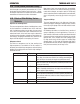
Figure 4-1: Thermal Arc 161 S Controls
SECTION 4:
OPERATION
Conventional operating procedures apply when using the
Welding Power Source, i.e. connect work lead directly to
work piece and electrode lead is used to hold the electrode.
The welding current range values should be used as a
guide only. Current delivered to the arc is dependent on
the welding arc voltage, and as welding arc voltage varies
between different classes of electrode, welding current at
any one setting would vary according to the type of elec-
trode in use. The operator should use the welding current
range values as a guide then fine tune the welding current
to suit the specific application. Refer to the electrode
manufacture's literature for further information.
4.01 Front Panel
Front Panel
The welding power source is protected by a self re-setting
thermostat. The indicator will illuminate if the duty cycle
of the power source has been exceeded. If the Over Heat
light illuminates wait for the Over Heat light to extinguish
before resuming welding.
(A) Process Selection Switch
Switches between LIFT TIG and STICK Welding modes.
(B) Power On Indicator
The Power ON Indicator illuminates when the ON/OFF
switch is in the ON position and the nominal mains volt-
age is present.
(C) Fault Indicator
The welding power source is protected by a self resetting
thermostat and over primary current protection devices.
Welding can not take place if the Fault Indicator lights up
or lights up continuously.
Thermostat Protection
If the Fault Indicator lights up then the duty cycle of the
power source has been exceeded, Leave the power on
and wait for the Warning Indicator to extinguish before
resuming welding.
Over Primary Current Protection
If the Fault Indicator lights up continuously then the
primary current into the main transformer has been ex-
ceeded. Have an Accredited Thermal Arc Service Provider
inspect then repair the welder.
(D) Welding Current Control
The welding current is increased by turning the Weld
Current control knob clockwise or decreased by turning
the Weld Current control knob counterclockwise. The
welding current should be set according to the specific
application. Refer to the electrode manufacture's literature
for further information.
(E) ON/OFF Switch (located on rear panel - not
shown)
This switch controls the Mains Supply Voltage to the
Power Source.
Art# A-09884
(B) Power On
Indicator
(C) Fault
Indicator
(A) Process
Selection
Switch
(D) Welding
Current
ǂ Control