
Owner's manual


TRANSARC 170i
INSTALLATION, OPERATION AND SETUP 3-14 Manual 0-5281
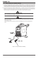
Installation
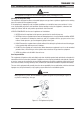
1. Remove cylinder valve plastic dust seal. Clean the cylinder valve outlet of impurities that may clog
orifices and damage seats before connecting the regulator.
Crack the valve (open then close) momentarily, pointing the outlet away from people and sources of
ignition. Wipe with a clean lint free cloth.
2. Match regulator to cylinder. Before connecting, check that the regulator label and cylinder marking
agree and that the regulator inlet and cylinder outlet match. NEVER CONNECT a regulator designed
for a particular gas or gases to a cylinder containing any other gas.
3. Connect the regulator inlet connection to cylinder or pipeline and tighten it firmly but not excessively,
with a suitable spanner.
4. Connect and tighten the outlet hose firmly and attach down-stream equipment.
5. To protect sensitive down-stream equipment a separate safety device may be necessary if the regulator
is not fitted with a pressure relief device.
Operation
With the regulator connected to cylinder or pipeline, and the adjustment screw/knob fully disengaged, pressurize
as follows:
1. Stand to one side of regulator and slowly open the cylinder valve. If opened quickly, a sudden pressure
surge may damage internal regulator parts.
2. With valves on downstream equipment closed, adjust regulator to approximate working pressure. It is
recommended that testing for leaks at the regulator connection points be carried out using a suitable
leak detection solution or soapy water.
3. Purge air or other unwanted welding grade shielding gas from equipment connected to the regulator
by individually opening then closing the equipment control valves. Complete purging may take up to
ten seconds or more, depending upon the length and size of the hose being purged.
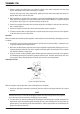
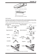
Adjusting Flow Rate
Art: A-05088_AB
Figure 3-6: Adjust Flow Rate
With the regulator ready for operation, adjust working flow rate as follows:
1. Slowly turn adjusting screw/knob in (clockwise) direction until the outlet gauge indicates the required
flow rate.
NOTE
It may be necessary to re-check the shielding gas regulator flow rate following the first weld sequence
due to back pressure present within shielding gas hose assembly.
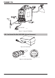
2. To reduce flow rate, allow the welding grade shielding gas to discharge from regulator by opening the
downstream valve. Bleed welding grade shielding gas into a well ventilated area and away from any
ignition source. Turn adjusting screw counterclockwise, until the required flow rate is indicated on the
gauge. Close downstream valve.