70Pi TRANSTIG welding Inverter A-11643 Operating Manual Revision: AA Operating Features: Issue Date: January 10, 2013 Manual No.
WE APPRECIATE YOUR BUSINESS! Congratulations on your new Cigweld product. We are proud to have you as our customer and will strive to provide you with the best service and reliability in the industry. This product is backed by our extensive warranty and world-wide service network. To locate your nearest distributor or service provider call +1300 654 674, or visit us on the web at www.cigweld.com.
! WARNINGS Read and understand this entire Manual and your employer’s safety practices before installing, operating, or servicing the equipment. While the information contained in this Manual represents the Manufacturer’s best judgement, the Manufacturer assumes no liability for its use.
TABLE OF CONTENTS SECTION 1: ARC WELDING SAFETY INSTRUCTIONS AND WARNINGS...................................... 1-1 1.01 1.02 1.03 Arc Welding Hazards........................................................................................ 1-1 Principal Safety Standards............................................................................... 1-5 Declaration of Conformity................................................................................ 1-6 SECTION 2: INTRODUCTION .......................
TABLE OF CONTENTS SECTION 6: KEY SPARE PARTS.................................................................................... 6-1 6.01 6.02 Power Source.................................................................................................. 6-1 TIG Torch W4014604....................................................................................... 6-3 APPENDIX: TRANSTIG 170Pi CIRCUIT DIAGRAM......................................................
TRANSTIG 170Pi SECTION 1: ARC WELDING SAFETY INSTRUCTIONS AND WARNINGS ! WARNING PROTECT YOURSELF AND OTHERS FROM POSSIBLE SERIOUS INJURY OR DEATH. KEEP CHILDREN AWAY. PACEMAKER WEARERS KEEP AWAY UNTIL CONSULTING YOUR DOCTOR. DO NOT LOSE THESE INSTRUCTIONS. READ OPERATING/INSTRUCTION MANUAL BEFORE INSTALLING, OPERATING OR SERVICING THIS EQUIPMENT.
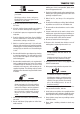
TRANSTIG 170Pi 2. Wear approved safety glasses. Side shields recommended. WARNING ARC RAYS can burn eyes and skin; NOISE can damage hearing. Arc rays from the welding process produce intense heat and strong ultraviolet rays that can burn eyes and skin. Noise from some processes can damage hearing. 1. Use a Welding Helmet or Welding Faceshield fitted with a proper shade of filter (see ANSI Z49.1 and AS 1674 listed in Safety Standards) to protect your face and eyes when welding or watching. 3.
TRANSTIG 170Pi 3. Remove all flammables within 35 ft (10.7 m) of the welding arc. If this is not possible, tightly cover them with approved covers. WARNING 4. Be alert that welding sparks and hot materials from welding can easily go through small cracks and openings to adjacent areas. FUMES AND GASES can be hazardous to your health. Welding produces fumes and gases. Breathing these fumes and gases can be hazardous to your health. 5. Watch for fire, and keep a fire extinguisher nearby. 6.
TRANSTIG 170Pi 5. Use only correct shielding gas cylinders, regulators, hoses, and fittings designed for the specific application; maintain them and associated parts in good condition. 6. Turn face away from valve outlet when opening cylinder valve. 7. Keep protective cap in place over valve except when cylinder is in use or connected for use. 8. Read and follow instructions on compressed gas cylinders, associated equipment, and CGA publication P-1 listed in Safety Standards.
TRANSTIG 170Pi 1.02 Principal Safety Standards Safety in Welding and Cutting, ANSI Standard Z49.1, from American Welding Society, 550 N.W. LeJeune Rd., Miami, FL 33126. Safety and Health Standards, OSHA 29 CFR 1910, from Superintendent of Documents, U.S. Government Printing Office, Washington, D.C. 20402. Recommended Safe Practices for the Preparation for Welding and Cutting of Containers That Have Held Hazardous Substances, American Welding Society Standard AWS F4.1, from American Welding Society, 550 N.W.
TRANSTIG 170Pi 1.03 Declaration of Conformity Manufacturer: CIGWELD Address: 71 Gower St, Preston Victoria 3072 Australia Description of equipment: Welding Equipment (GTAW, MMAW) including, but not limited to CIGWELD Transtig 170Pi Welding Inverter and associated accessories. Serial numbers are unique with each individual piece of equipment and details description, parts used to manufacture a unit and date of manufacture.
TRANSTIG 170Pi SECTION 2: INTRODUCTION 2.01 How To Use This Manual 2.02 Equipment Identification To ensure safe operation, read the entire manual, including the chapter on safety instructions and warnings. The unit’s identification number (specification or part number), model, and serial number usually appear on a nameplate attached to the control panel. In some cases, the nameplate may be attached to the rear panel.
TRANSTIG 170Pi 2.04 Symbol Chart Note that only some of these symbols will appear on your model. On Single Phase Wire Feed Function Off Three Phase Wire Feed Towards Workpiece With Output Voltage Off.
TRANSTIG 170Pi 2.05 Description 2.07 Transporting Methods The Cigweld Transtig 170Pi is a self contained single phase multi process welding inverter that is capable of performing MMAW (Stick) and GTAW (HF and Lift TIG) welding processes. The unit is equipped with an integrated voltage reduction device (VRD applicable in stick mode only), digital amperage/voltage meter, and a host of other features in order to fully satisfy the broad operating needs of the modern welding professional.
TRANSTIG 170Pi 2.09 Duty Cycle The rated duty cycle of a Welding Power Source, is a statement of the time it may be operated at its rated welding current output without exceeding the temperature limits of the insulation of the component parts. To explain the 10 minute duty cycle period the following example is used. Suppose a Welding Power Source is designed to operate at a 30% duty cycle, 170 amperes at 26.8 volts. This means that it has been designed and built to provide the rated amperage (170A) for 3.
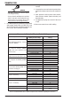
TRANSTIG 170Pi 2.10 Specifications Description Transtig 170Pi W1007190 Plant Part No Power Source Part No Power Source Dimensions Power Source Mass Cooling Welder Type Australian Standard Number of Phases Nominal Supply Voltage W1007189 H324mmxW122mmxD458mm 11.5 KG Fan Cooled Multi Process Inverter Power Source AS 60974.1-2006 / IEC 60974.
TRANSTIG 170Pi NOTE 4 Minimum Generator Recommendation at the Maximum Output Duty Cycle. Due to large variations in performance and specifications of different brands and types of generators, Cigweld cannot guarantee full welding output power or duty cycle on every brand or type of generator. Some small generators incorporate low cost circuit breakers on their outputs. These circuit breakers usually will have a small reset button, and will trip much faster than a switchboard type circuit breaker.
TRANSTIG 170Pi SECTION 3: INSTALLATION, OPERATION AND SETUP 3.01 Environment These units are designed for use in environments with increased hazard of electric shock as outlined in AS 60974.1 and AS 1674.2. A. Examples of environments with increased hazard of electric shock are: 1. In locations in which freedom of movement is restricted, so that the operator is forced to perform the work in a cramped (kneeling, sitting or lying) position with physical contact with conductive parts. 2.
TRANSTIG 170Pi C. Methods of Reducing Electromagnetic Emissions action may be as simple as earthing the welding circuit, see NOTE below. In other cases it could involve constructing an electromagnetic screen enclosing the Welding Power Source and the work, complete with associated input filters. In all cases, electromagnetic disturbances shall be reduced to the point where they are no longer troublesome. 1.
TRANSTIG 170Pi bonding the workpiece to earth may reduce emissions in some, but not all instances. Care should be taken to prevent the earthing of the workpiece increasing the risk of injury to users, or damage to other electrical equipment.
TRANSTIG 170Pi The display will also show error code E-1 if the “Fail to Safe” protection has operated. A-11690 2. Digital Meter (Amps and Volts) The digital meter is used to display the pre-set parameter values (when not welding) and actual output current or voltage (when welding) of the power source. A long press (>2s) on the Multi Function Control toggles between the display of amps and volts.
TRANSTIG 170Pi A-11647 Figure 3-3: Programming Mode STICK Programming Mode Programming Parameter Control Panel Display Hot Start This para me te r operates in STICK mode to improve the start characteristics for stick electrodes HOT START current is on top of the BASE current. e.g. HOT START current = 130 amps when BASE (WELD) = 100 amps & HOT START = 30 amps Range is 0 to 70A. Factory default is 20A. Note that maximum weld current is 170A. Base Current This parameter sets the STICK weld current.
TRANSTIG 170Pi Programming Parameter Control Panel Display Arc Force Arc Force is effective when in STICK mode only. Arc Force control provides an adjustable amount of Arc Force (or "dig") control. This feature can be particularly beneficial in providing the operator the ability to compensate for variability in joint fit-up in certain situations with particular electrodes. In general increasing the Arc Force control toward 100% (maximum Arc Force) allows greater penetration control to be achieved.
TRANSTIG 170Pi Up Slope This parameter operates in TIG modes only and is used to set the time for the weld current to ramp up from INITIAL current to BASE current. Range is 0.0 to 15.0 seconds. Factory default is 1.0 second. Base Current In DC TIG mode, this parameter sets the TIG welding current. In PULSE TIG mode, this parameter sets the PEAK current. Range is 5 to 170A. Factory default is 120A.
TRANSTIG 170Pi Pulse Mode / Direct DC mode This parameter selects PULSE operating mode or DIRECT DC (-) operating mode. Range is DC or Pulse Mode. Factory default is DC. Trough Current This parameter sets the TIG TROUGH current. The lowest point in the pulse is called the Trough. Range is 5 to base current level. Factory default is 80A.
TRANSTIG 170Pi Pulse Width This parameter sets the percentage “on” time of the PULSE FREQUENCY for BASE weld current when in PULSE operating mode. Range is 15 to 80%. Factory default is 50%. Pulse Frequency This parameter sets the PULSE FREQUENCY when in PULSE operating mode. Range is 0.5 to 500Hz. Factory default is 100Hz. Down Slope This parameter operates in TIG modes only and is used to set the time for the weld current to ramp down to the crater current.
TRANSTIG 170Pi Crater Current This parameter operates in TIG modes only. In 2T mode this is the current at the end of the down slope current ramp. When the welding current reaches the Crater Current value, the welding current will cease and the unit will enter Post Flow mode. In 4T mode, this is the current at the end of the down slope current ramp.
TRANSTIG 170Pi CAUTION Loose welding terminal connections can cause overheating and result in the male plug being fused in the bayonet terminal. 7. Remote Control Socket The 8 pin Remote Control Socket is used to connect remote control devices to the welding power source. To make connections, align keyway, insert plug, and rotate threaded collar fully clockwise.
TRANSTIG 170Pi A-11663 4T Latch Mode This mode of welding is mainly used for long welding runs to reduce operator fatigue. In this mode the operator can press and release the torch trigger and the output will remain active. To deactivate the power source, the trigger switch must again be depressed and released, thus eliminating the need for the operator to hold the torch trigger.
TRANSTIG 170Pi Note that when the unit is powered on the mode selection control will automatically default to LIFT TIG/HF TIG mode. This is necessary so as to prevent inadvertent arcing should an electrode holder be connected to the unit and mistakenly be in contact with the work piece during power up. 11. Thermal Overload Indicator This welding power source is protected by a self resetting thermostat. The indicator will illuminate if the duty cycle of the power source has been exceeded.
TRANSTIG 170Pi 3.07 Shielding Gas Regulator Operating Instructions ! WARNING This equipment is designed for use with welding grade (Inert) shielding gases only. Shielding Gas Regulator Safety This regulator is designed to reduce and control high pressure gas from a cylinder or pipeline to the working pressure required for the equipment using it. If the equipment is improperly used, hazardous conditions are created that may cause accidents. It is the users responsibility to prevent such conditions.
TRANSTIG 170Pi Installation 1. Remove cylinder valve plastic dust seal. Clean the cylinder valve outlet of impurities that may clog orifices and damage seats before connecting the regulator. Crack the valve (open then close) momentarily, pointing the outlet away from people and sources of ignition. Wipe with a clean lint free cloth. 2. Match regulator to cylinder. Before connecting, check that the regulator label and cylinder marking agree and that the regulator inlet and cylinder outlet match.
TRANSTIG 170Pi Shutdown Close cylinder valve whenever the regulator is not in use. To shut down for extended periods (more than 30 minutes). 1. Close cylinder or upstream valve tightly. 2. Open downstream equipment valves to drain the lines. Bleed gas into a well ventilated area and away from any ignition source. 3. After gas is drained completely, disengage adjusting screw and close downstream equipment valves. 4.
TRANSTIG 170Pi A-11666 Figure 3-7: Setup for TIG Welding 3.09 Foot Control Part No.
TRANSTIG 170Pi Description The CIGWELD Foot Control is a foot operated switch and potentiometer which starts and stops the welding process and controls welding current through operation of the foot pedal. Refer to list below for compatible Cigweld power sources. Installation Attach the 8-pin connector on the end of the cable to the 8-pin receptacle on the front of the welding machine. To complete the connection, align the keyway, insert the plug, and rotate the threaded collar fully clockwise.
TRANSTIG 170Pi 3.10 Setup for Manual Arc (MMAW) Welding A. Connect the Electrode Holder lead to the positive welding terminal (+). If in doubt, consult the electrode manufacturer. Welding current flows from the Power Source via heavy duty bayonet type terminals. It is essential, however, that the male plug is inserted and turned securely to achieve a sound electrical connection. B. Connect the work lead to the negative welding terminal (-). If in doubt, consult the electrode manufacturer.
TRANSTIG 170Pi INSTALLATION, OPERATION AND SETUP 3-20 Manual 0-5241
TRANSTIG 170Pi SECTION 4: BASIC WELDING GUIDE 4.01 Stick (MMAW) Basic Welding Technique Size of Electrode The electrode size is determined by the thickness of metals being joined and can also be governed by the type of welding machine available. Small welding machines will only provide sufficient current (amperage) to run the smaller size electrodes. For thin sections, it is necessary to use smaller electrodes otherwise the arc may burn holes through the job.
TRANSTIG 170Pi Welding Position The electrodes dealt with in this publication can be used in most positions, i.e. they are suitable for welding in flat, horizontal, vertical and overhead positions. Numerous applications call for welds to be made in positions intermediate between these. Some of the common types of welds are shown in Figures 4-1 through 4-8.
TRANSTIG 170Pi Art# A-07693 Figure 4-7: Overhead Position, Butt Weld Art # A-07694 Figure 4-8: Overhead Position, Fillet Weld Joint Preparations In many cases, it will be possible to weld steel sections without any special preparation. For heavier sections and for repair work on castings, etc., it will be necessary to cut or grind an angle between the pieces being joined to ensure proper penetration of the weld metal and to produce sound joints.
TRANSTIG 170Pi Arc Welding Technique - A Word to Beginners For those who have not yet done any welding, the simplest way to commence is to run beads on a piece of scrap plate. Use mild steel plate about 6.0mm thick and a 3.2mm electrode. Clean any paint, loose scale or grease off the plate and set it firmly on the work bench so that welding can be carried out in the downhand position. Make sure that the work clamp is making good electrical contact with the work, either directly or through the work table.
TRANSTIG 170Pi If the travel is too fast, the bead will be narrow and strung out and may even be broken up into individual globules. If the travel is too slow, the weld metal piles up and the bead will be too large. Making Welded Joints Having attained some skill in the handling of an electrode, you will be ready to go on to make up welded joints. A. Butt Welds Set up two plates with their edges parallel, as shown in Figure 4-11, allowing 1.6mm to 2.4mm gap between them and tack weld at both ends.
TRANSTIG 170Pi from the vertical. Some electrodes require to be sloped about 20º away from the perpendicular position to prevent slag from running ahead of the weld. Refer to Figure 4-13. Do not attempt to build up much larger than 6.4mm width with a 3.2mm electrode, otherwise the weld metal tends to sag towards the base, and undercut forms on the vertical leg. Multi-runs can be made as shown in Figure 4-14. Weaving in HV fillet welds is undesirable.
TRANSTIG 170Pi Art # A-07702 Figure 4-16: Multi Run Vertical Fillet Weld Art # A-07703 Figure 4-17: Examples of Vertical Fillet Welds 2. Vertical Down The Ferrocraft 21 electrode makes welding in this position particularly easy. Use a 3.2mm electrode at 100 amps. The tip of the electrode is held in light contact with the work and the speed of downward travel is regulated so that the tip of the electrode just keeps ahead of the slag. The electrode should point upwards at an angle of about 45º. 3.
TRANSTIG 170Pi Distortion Distortion in some degree is present in all forms of welding. In many cases it is so small that it is barely perceptible, but in other cases allowance has to be made before welding commences for the distortion that will subsequently occur. The study of distortion is so complex that only a brief outline can be attempted hear. The Cause of Distortion Distortion is caused by: A.
TRANSTIG 170Pi B. Distribution of Stresses Distortion may be reduced by selecting a welding sequence which will distribute the stresses suitably so that they tend to cancel each other out. See Figures 4-20 through 4-23 for various weld sequences. Choice of a suitable weld sequence is probably the most effective method of overcoming distortion, although an unsuitable sequence may exaggerate it. Simultaneous welding of both sides of a joint by two welders is often successful in eliminating distortion. C.
TRANSTIG 170Pi 3 2 1 Art # A-07710_AB Block Sequence. The spaces between the welds are filled in when the welds are cool.
TRANSTIG 170Pi Electrode Selection Chart Description Diameter CIGWELD Electrode Selection Chart Pack Part No. Application 2.5mm 2.5mm 3.2mm 3.2mm 4.0mm 2.0mm 2.0mm 2.5mm 2.5mm 3.2mm 3.2mm 4.0mm 2.0mm 2.0mm 2.5mm 2.5mm 2.5mm 3.2mm 3.2mm 3.2mm 4.0mm 2.5mm 3.2mm 4.0mm 2.5mm 3.2mm 4.0mm 2.5mm 3.2mm 4.0mm 2.0mm 2.5mm 3.2mm 2.5/3.2mm 4.0mm 2.5mm 3.2mm 2.5/3.2mm 4.0mm 1kg 2.5kg 1kg 2.5kg 5kg 1kg 2.5kg 1kg 2.5kg 1kg 2.5kg 5kg 1 kg 2.5 kg 1 kg 2.5 kg 5 kg 1 kg 2.5 kg 5 kg 5 kg 5 kg 5 kg 5 kg 2.5 kg 2.5 kg 2.
TRANSTIG 170Pi 4.02 Stick (MMAW) Welding Troubleshooting FAULT 1 Welding current varying CAUSE REMEDY ARC FORCE is set at a value that causes the welding current to vary excessively with the arc length. A Welding current too low 2 A gap is left by failure of the weld B Electrode too large for metal to fill the joint. root of the weld. C Insufficient gap.
TRANSTIG 170Pi 5 Portions of the A Small electrodes used on A Use larger electrodes and preheat the plate. weld run do not heavy cold plate. fuse to the surface B Welding current is too low. B Increase welding current. of the metal or C Adjust angle so the welding arc is directed more edge of the joint. C Wrong electrode angle. into the base metal. D Travel speed of electrode is too high. D Reduce travel speed of electrode. E Scale or dirt on joint surface. E Clean surface before welding.
TRANSTIG 170Pi 4.03 TIG (GTAW) Basic Welding Technique Gas Tungsten Arc Welding (GTAW) or TIG (Tungsten Inert Gas) as it is commonly referred to, is a welding process in which fusion is produced by an electric arc that is established between a single tungsten (nonconsumable) electrode and the work piece. Shielding is obtained from a welding grade shielding gas or welding grade shielding gas mixture which is generally Argon based.
TRANSTIG 170Pi Tungsten Electrode Types Electrode Type (Ground Finish) Welding Application Features Colour Code Thoriated 2% DC welding of mild steel, stainless steel and copper Excellent arc starting, Long life, High current carrying capacity Red Zirconated 1% High quality AC welding of aluminium, magnesium and their alloys. Self cleaning, Long life, Maintains balled end, High current carrying capacity.
TRANSTIG 170Pi TIG Welding is generally regarded as a specialised process that requires operator competency. While many of the principles outlined in the previous Arc Welding section are applicable a comprehensive outline of the TIG Welding process is outside the scope of this Operating Manual. For further information please refer to www. cigweld.com.au or contact Cigweld. 4.04 TIG (GTAW) Welding Problems FAULT CAUSE REMEDY 1 Excessive bead build up or poor penetration or poor fusion at edges of weld.
TRANSTIG 170Pi 7 Dirty weld pool A Electrode contaminated A Clean the electrode by grinding off the by contact with work contaminates. piece or filler rod material. B Work piece surface has B Clean surface. foreign material on it. C Gas contaminated with C Check gas lines for cuts and loose fitting air. or change gas cylinder. 8 Poor weld finish 9 Arc start is not smooth. Inadequate shielding gas. Increase gas flow or check gas line for gas flow problems.
TRANSTIG 170Pi BASIC WELDING GUIDE 4-18 Manual 0-5241
TRANSTIG 170Pi SECTION 5: POWER SOURCE PROBLEMS AND ROUTINE SERVICE REQUIREMENTS 5.01 Power Source Problems FAULT CAUSE REMEDY 1 Mains supply voltage is ON, A Power source is not in the Amps Display is illumicorrect mode of operation. nated however unit will not commence welding when B Faulty torch trigger. the torch trigger switch is depressed. A Set the power source to the correct mode of operation with the process selection switch. Duty cycle of power source has been exceeded.
TRANSTIG 170Pi 10 Fault light is on, and E-1 is A Fail to Safe protection has shown on the Amps display operated in STICK modeVRD fault. A Reset mains power, if fault does not clear then have an accredited CIGWELD service provider repair unit. B Fail to Safe protection has operated in TIG mode- Inverter fault. B Reset mains power, if fault does not clear then have an accredited CIGWELD service provider repair unit. C External voltage has been applied to the welding circuit.
TRANSTIG 170Pi Minimum Insulation Resistance (MΩ) Components to be Tested Input circuit (including any connected control circuits) to welding circuit (including any connected control circuits) 5 All circuits to exposed conductive parts 2.
TRANSTIG 170Pi F. Accessories Accessory equipment, including output leads, electrode holders, torches, wire feeders and the like shall be inspected at least monthly by a competent person to ensure that the equipment is in a safe and serviceable condition. All unsafe accessories shall not be used. G. Repairs If any parts are damaged for any reason, it is recommended that replacement be performed by an accredited Cigweld Service Provider. Power Source Calibration A.
TRANSTIG 170Pi 5.03 Cleaning the Welding Power Source ! WARNING There are dangerous voltage and power levels present inside this product. Do not attempt to open or repair unless you are a qualified electrical tradesperson. Disconnect the Welding Power Source from the Mains Supply Voltage before disassembling. To clean the Welding Power Source, open the enclosure and use a vacuum cleaner to remove any accumulated dirt, metal filings, slag and loose material. 5.
TRANSTIG 170Pi POWER SOURCE PROBLEMS AND ROUTINE SERVICE REQUIREMENTS 5-6 Manual 0-5241
TRANSTIG 170Pi SECTION 6: KEY SPARE PARTS 6.
TRANSTIG 170Pi TRANSTIG 170Pi POWER SOURCE SPARE PARTS ITEM 1 2 3 4 5 6 PART NUMBER W7005815 W7005801 W7005802 W7005803 W7005805 W7004909 7 W7005811 8 9 10 11 12 13 14 15 16 17 W7005812 W7005804 W7005814 W7004908 W7005605 W7005813 W7004913 W7005806 W7003010 704461 KEY SPARE PARTS DESCRIPTION PCB Power PCB Control PCB HF Generator PCB Front Panel (Display) Knob Control Dinse Socket 50mm2 Control Socket 8 pin (Note that 8 pin control plug is part number UOA706900) Shielding Gas Outlet 5/8-18 HF Couplin
TRANSTIG 170Pi 6.02 TIG Torch W4014604 TIG Torch W4014604 spare parts diagram A-11669 Figure 6-2 TIG TORCH SPARE PARTS ITEM PART NO.
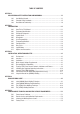
A-1 E N A WELD NEGATIVE OT1 OT2 WELD POSITIVE DY DY1 NEGATIVE INPUT RECTIFIER POSITIVE MAIN CONTROL BOARD SOURCE DRIVE QF TH1 DY2 NEUTRAL CY1 4R 50W R2 J1 IN FJ SOLENOID EMC FILTER NEGATIVE 24VDC FAN SW1 ACTIVE PFC JC L4 R56 R39 GUN GUN OUT V8 V7 C21 C20 IFB FILTER C19 C17 HF WV Manual 0-5241 C25 C24 C23 C22 CT1 DISPLAY BOARD 8 PIN REMOTE TORCH TRIGGER GUN IN Q2 Q1 T1 ACTIVE NEUTRAL C101 C100 HF 220V R101, 103 T18 T14 R100, 102 COUT2 COUT
CIGWELD - LIMITED WARRANTY TERMS LIMITED WARRANTY: CIGWELD Pty Ltd, A Victor Technologies Company, hereafter, “CIGWELD” warrants to customers of its authorized distributors hereafter “Purchaser” that its products will be free of defects in workmanship or material.
TERMS OF WARRANTY – January 2013 1. The Trade Practices Act 1974 (Commonwealth) and similar State Territory legislation relating to the supply of goods and services, protects consumers’ interests by ensuring that consumers are entitled in certain situations to the benefit of various conditions, warranties, guarantees, rights and remedies (including warranties as to merchantability and fitness for purpose) associated with the supply of goods and services.
WARRANTY SCHEDULE – January 2013 These warranty periods relate to the warranty conditions in clause 2. All warranty periods are from date of sale from the Accredited Distributor of the equipment. Notwithstanding the foregoing, in no event shall the warranty period extend more than the time stated plus one year from the date CIGWELD delivered the product to the Accredited Distributor. Unless otherwise stated the warranty period includes parts and labour.
Australia Terms of Warranty – 2013 Effective 1st January 2012, all warranties against defects (also known as a manufacturer’s warranty) supplied with goods or services must comply with the new Australian consumer law regulations (2010). This Warranty Statement should be read in conjunction with the Warranty Schedule contained in the operating instructions of the product.
GLOBAL CUSTOMER SERVICE CONTACT INFORMATION CIGWELD, Australia 71 Gower Street Preston, Victoria Australia, 3072 Telephone: 61-3-9474-7400 Fax: 61-3-9474-7391 Email: enquiries@cigweld.com.au Victor Technologies USA 2800 Airport Road Denton, Tx 76207 USA Telephone: (940) 566-2000 800-426-1888 Fax: 800-535-0557 Email: sales@thermalarc.
Asia Pacific Regional Headquarters 71 Gower Street Preston, Victoria, Australia, 3072 Telephone: +61 3 9474 7400 +61 3 9474 7391 FAX: Email: enquiries@cigweld.com.au www.cigweld.com.