
Owner manual


Manual 0-4964 Rev AA.01
February 5, 2007
1
Unpacking
The product is packaged and protected to prevent damage
during shipping. Inspect for possible shipping damage. If
damage is evident, contact your distributor and/or shipping
company before proceeding with installation.
General Information
This kit is for use only with Thermal Dynamics UltraCut
®
Power Supplies and XT-300 Torches. Do not use this kit
with any other equipment.
This kit requires the C.C.M. (Communication Control Mod-
ule) Firmware to have version 3.2 or higher and a change
in DIP switch settings. See your authorised service center
for this update.
This kit requires the GCM 2010 Firmware to be 3.1 or high-
er. See your authorised service center for this update.
This kit accepts prefl ow, plasma, shield and Water Mist
Secondary™ gases from the Gas Control Module and
supplies these gases to the Torch.
Supplied Parts
• XTL Torch Valve Assembly
• 4’ Plasma Hose
• 4’ Shield Hose
• 4 Fuses
• Fuse Rating Label
• Installation Instructions
Manual 0-4964
XTL Torch Valve Kit No. 4-3054
Installation Instructions
82 Benning Street, West Lebanon, NH 03784 USA
(603) 298-5711 • www.thermal-dynamics.com
© 2007 Thermadyne Corp.
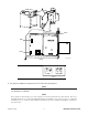
Art # A-07644
4.31 in
109 mm
2.9 in
73.66 mm
3.72 in
95 mm
5 in
127 mm
Installation
WARNINGS
Disconnect primary power at the source.
1. In most cases the XTL Valve Kit may be mounted in the
same location as the old one. If not, mount it as close
as possible to the Torch. The valve kit can be mounted
in any convenient position, provided the outlet side
(with two fi ttings) is closer to the torch than the inlet
side (with four fi ttings and a control cable connector).
Dimensions given in the following illustration are to as-
sist in locating mounting holes and hardware length.
NOTE
Care must be taken when considering the
mounting location so the exhaust muffler
on top of the assembly is not covered or
blocked.