
Owner's manual


October 7, 2010 1 Manual 0-5121 Rev. AA
Scope
This kit is for use only with the following Thermal Dy-
namics Plasma Cutting Systems:
Do not use this kit with any other equipment.
CutMaster 52,82,102,152
CutMaster 12mm,20mm,25mm,35mm, 40mm
CutMaster A40, A60,A80,A120
Supplied Parts
The kits include:
• Automation Interface Pcb 9-8388
• Wire Harness
• (2) #6-32x3/8 Pan Head Screws
• (2) M4x10mm Torx Head Screws
• Installation Instructions
Instructions
WARNINGS
Disconnect primary power at the source before
performing any inspection or repairs.
Only a qualifi ed technician should perform this
procedure.
Follow the electrostatic discharge instructions
included with the component to prevent damage
to the component.
Manual 0-5121
Automation Interface Kit No. 9-8311
For CutMaster True Series
Installation Instructions
© 2008 Thermadyne Corp.
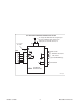
Installation Procedure
1. Remove the power supply cover.
2. Connect the supplied harness to the Automation
Interface Pcb by attaching the Fast-on terminal onto
the mating male terminal and the 8 socket receptacle
onto the P2 connector.
3. Remove the lower hole plug from the rear panel.