ARCMASTER 401MST Operating Manual Art # A-12449_AB Revision: AB Issue Date: June 17, 2014 Manual No.: 0-5287 3163339 Tweco.
WE APPRECIATE YOUR BUSINESS! Congratulations on receiving your new Tweco product. We are proud to have you as our customer and will strive to provide you with the best service and support in the industry. This product is backed by our extensive warranty and world-wide service network. We know you take pride in your work and we feel privileged to provide you with this high performance product that will help you get the job done.
! WARNINGS Read and understand this entire Manual and your employer’s safety practices if applicable before installing, operating, or servicing the equipment. While the information contained in this Manual represents the Manufacturer’s best judgment, the Manufacturer assumes no liability for its use. Operating Manual Number 0-5287 for: Tweco ArcMaster 401MST Power Source Part Number W1009500 Published by: Victor Technologies, Inc. 16052 Swingley Ridge Road, Suite 300 St. Louis, MO 63017 USA www.
TABLE OF CONTENTS SECTION 1: SAFETY INSTRUCTIONS AND WARNINGS................................................ 1-1 1.01 1.02 1.03 1.04 1.05 1.06 1.07 1.08 1.09 Arc Welding Hazards........................................................................................ 1-1 General Safety Information for Victor Regulator................................................ 1-5 Principal Safety Standards............................................................................... 1-7 Symbol Chart..................
TABLE OF CONTENTS SECTION 4: BASIC WELDING GUIDE ..................................................................... 4-1 4.01 4.02 4.03 4.04 Stick (SMAW) Basic Welding Technique.......................................................... 4-1 Stick (SMAW) Welding Troubleshooting........................................................ 4-10 TIG (GTAW) Basic Welding Technique........................................................... 4-12 TIG (GTAW) Welding Problems.............................................
ARCMASTER 401MST POWER SOURCE SECTION 1: SAFETY INSTRUCTIONS AND WARNINGS ! WARNING PROTECT YOURSELF AND OTHERS FROM POSSIBLE SERIOUS INJURY OR DEATH. KEEP CHILDREN AWAY. PACEMAKER WEARERS KEEP AWAY UNTIL CONSULTING YOUR DOCTOR. DO NOT LOSE THESE INSTRUCTIONS. READ OPERATING/INSTRUCTION MANUAL BEFORE INSTALLING, OPERATING OR SERVICING THIS EQUIPMENT.
ARCMASTER 401MST POWER SOURCE 3. Use protective screens or barriers to protect others from flash and glare; warn others not to watch the arc. WARNING 4. Wear protective clothing made from durable, flame-resistant material (wool and leather) and foot protection. ARC RAYS can burn eyes and skin; NOISE can damage hearing. Arc rays from the welding process produce intense heat and strong ultraviolet rays that can burn eyes and skin. Noise from some processes can damage hearing. 5.
ARCMASTER 401MST POWER SOURCE 1. Keep your head out of the fumes. Do not breathe the fumes. 6. Be aware that welding on a ceiling, floor, bulkhead, or partition can cause fire on the hidden side. 2. If inside, ventilate the area and/or use exhaust at the arc to remove welding fumes and gases. 7. Do not weld on closed containers such as tanks or drums. 3. If ventilation is poor, use an approved air-supplied respirator. 8.
ARCMASTER 401MST POWER SOURCE 7. Keep protective cap in place over valve except when cylinder is in use or connected for use. 3. Have only qualified people remove guards or covers for maintenance and troubleshooting as necessary. 8. Read and follow instructions on compressed gas cylinders, associated equipment, and CGA publication P-1 listed in Safety Standards. ! 4. To prevent accidental starting during servicing, disconnect negative (-) battery cable from battery. 5.
ARCMASTER 401MST POWER SOURCE ! 1.02 General Safety Information for Victor Regulator WARNING A Fire Prevention Welding and cutting operations use fire or combustion as a basic tool. The process is very useful when properly controlled. However, it can be extremely destructive if not performed correctly in the proper environment. WARNING: This product contains chemicals, including lead, known to the State of California to cause birth defects and other reproductive harm. Wash hands after handling.
ARCMASTER 401MST POWER SOURCE C E Compressed Gas Cylinders The Department of Transportation (DOT) approves the design and manufacture of cylinders that contain gases used for welding or cutting operations. Ventilation ! WARNING Adequately ventilate welding, heating, and cutting work areas to prevent accumulation of explosive or toxic concentrations of gases. Certain combinations of metals, coatings, and gases generate toxic fumes. Use respiratory protection equipment in these circumstances.
ARCMASTER 401MST POWER SOURCE 1.03 Principal Safety Standards 4. NEVER use compressed gas cylinders without a pressure reducing regulator attached to the cylinder valve. Safety in Welding and Cutting, ANSI Standard Z49.1, from American Welding Society, 550 N.W. LeJeune Rd., Miami, FL 33126. 5. Inspect the cylinder valve for oil, grease, and damaged parts. ! Safety and Health Standards, OSHA 29 CFR 1910, from Superintendent of Documents, U.S. Government Printing Office, Washington, D.C. 20402.
ARCMASTER 401MST POWER SOURCE 1.04 Symbol Chart Note that only some of these symbols will appear on your model. On Single Phase Wire Feed Function Off Three Phase Wire Feed Towards Workpiece With Output Voltage Off.
ARCMASTER 401MST POWER SOURCE 1.05 Precautions De Securite En Soudage A L’arc ! MISE EN GARDE LE SOUDAGE A L’ARC EST DANGEREUX PROTEGEZ-VOUS, AINSI QUE LES AUTRES, CONTRE LES BLESSURES GRAVES POSSIBLES OU LA MORT. NE LAISSEZ PAS LES ENFANTS S’APPROCHER, NI LES PORTEURS DE STIMULATEUR CARDIAQUE (A MOINS QU’ILS N’AIENT CONSULTE UN MEDECIN). CONSERVEZ CES INSTRUCTIONS. LISEZ LE MANUEL D’OPERATION OU LES INSTRUCTIONS AVANT D’INSTALLER, UTILISER OU ENTRETENIR CET EQUIPEMENT.
ARCMASTER 401MST POWER SOURCE 9. N’enroulez pas de câbles électriques autour de votre corps. AVERTISSEMENT 10. N’utilisez qu’une bonne prise de masse pour la mise à la terre de la pièce à souder. LE RAYONNEMENT DE L’ARC PEUT BRÛLER LES YEUX ET LA PEAU; LE BRUIT PEUT ENDOMMAGER L’OUIE. 11. Ne touchez pas à l’électrode lorsqu’en contact avec le circuit de soudage (terre). L’arc de soudage produit une chaleur et des rayons ultraviolets intenses, susceptibles de brûler les yeux et la peau.
ARCMASTER 401MST POWER SOURCE 2. Portez des lunettes de sécurité approuvées. Des écrans latéraux sont recommandés. AVERTISSEMENT 3. Entourez l’aire de soudage de rideaux ou de cloisons pour protéger les autres des coups d’arc ou de l’éblouissement; avertissez les observateurs de ne pas regarder l’arc. LE SOUDAGE PEUT CAUSER UN INCENDIE OU UNE EXPLOSION L’arc produit des étincellies et des projections.
ARCMASTER 401MST POWER SOURCE AVERTISSEMENT LES ETINCELLES ET LES PROJECTIONS BRULANTES PEUVENT CAUSER DES BLESSURES. 8. Lisez et respectez les consignes relatives aux bouteilles de gaz comprimé et aux équipements connexes, ainsi que la publication P-1 de la CGA, identifiée dans la liste de documents ci-dessous. AVERTISSEMENT Le piquage et le meulage produisent des particules métalliques volantes. En refroidissant, la soudure peut projeter du éclats de laitier.
ARCMASTER 401MST POWER SOURCE 5. Utilisez la polarité correcte (+ et –) de l’accumulateur. AVERTISSEMENT DES PIECES EN MOUVEMENT PEUVENT CAUSER DES BLESSURES. AVERTISSEMENT LA VAPEUR ET LE LIQUIDE DE REFROIDISSEMENT BRULANT SOUS PRESSION PEUVENT BRULER LA PEAU ET LES YEUX. Des pièces en mouvement, tels des ventilateurs, des rotors et des courroies peuvent couper doigts et mains, ou accrocher des vêtements amples. 1.
ARCMASTER 401MST POWER SOURCE des faits scientifiques visant à atténuer ou éviter des risques potentiels ». ! Pour atténuer les champs magnétiques sur les lieux de travail, respectez les procédures qui suivent : N’effectuez JAMAIS d’opérations de soudage sur un récipient qui a contenu des liquides ou vapeurs toxiques, combustibles ou inflammables. N’effectuez JAMAIS d’opérations de soudage dans une zone contenant des vapeurs combustibles, des liquides inflammables ou des poussières explosives. 1.
ARCMASTER 401MST POWER SOURCE AVIS Ce document CGA p. t peut être obtenu en écrivant à “Compressed Gas Association”, 4221 Walney Roed, 5th Floor. Chantilly, VA 20151.2923, USA. manches et poches boutonnés. Il ne faut pas remonter vos manches ou les pantalons à revers. Quand vous travaillez dans un environnement non dédié au soudage ou découpage, portez toujours une protection des yeux appropriées ou un masque facial. ! 2.
ARCMASTER 401MST POWER SOURCE 1.08 Principales Normes De Securite Safety in Welding and Cutting, norme ANSI Z49.1, American Welding Society, 550 N.W. LeJeune Rd., Miami, FL 33128. Safety and Health Standards, OSHA 29 CFR 1910, Superintendent of Documents, U.S. Government Printing Office, Washington, D.C. 20402. Recommended Safe Practices for the Preparation for Welding and Cutting of Containers That Have Held Hazardous Substances, norme AWS F4.1, American Welding Society, 550 N.W. LeJeune Rd.
ARCMASTER 401MST POWER SOURCE 1.09 Graphique de Symbole Seulement certains de ces symboles apparaîtront sur votre modèle.
ARCMASTER 401MST POWER SOURCE This Page Intentionally Blank SAFETY INSTRUCTIONS AND WARNINGS 1-18 Manual 0-5287
ARCMASTER 401MST POWER SOURCE SECTION 2: INTRODUCTION 2.01 How To Use This Manual 2.02 Equipment Identification To ensure safe operation, read the entire manual, including the chapter on safety instructions and warnings. The unit’s identification number (specification or part number), model, and serial number usually appear on a nameplate attached to the control panel. In some cases, the nameplate may be attached to the rear panel.
ARCMASTER 401MST POWER SOURCE 2.04 Description 2.06 Transporting Methods The Tweco ArcMaster 401MST is a welding power source incorporating to provide Lift TIG, MIG & FCAW, Stick, and Gouging welding process. ! Disconnect input power conductors from de-energized supply line before moving the welding Power Source. The units are also fully compliant to CSA E 60974-1 and UL 60974-1. Lift Power Source with handle on top of case. Use handcart or similar device of adequate capacity.
ARCMASTER 401MST POWER SOURCE 2.08 Duty Cycle The rated duty cycle of a Welding Power Source, is a statement of the time it may be operated at its rated welding current output without exceeding the temperature limits of the insulation of the component parts. To explain the 10 minute duty cycle period the following example is used. Suppose a Welding Power Source is designed to operate at a 40% duty cycle, 170 amperes at 26.8 volts.
ARCMASTER 401MST POWER SOURCE 2.09 Specifications Description Power Source Part Number Power Source Mass Power Source Dimensions Cooling Welder Type Output Terminal Type Standards Number of Phases Nominal Supply Voltage Nominal Supply Frequency Welding Current Range Effective Input Current (I1eff) (note2) Maximum Input Current (I1max) Generator Requirement (note4) STICK (SMAW) Welding Output, 40ºC, 10 min. Lift TIG (GTAW) Welding Output, 40ºC, 10 min. MIG & FCAW (GMAW FCAW) Welding Output, 40ºC, 10 min.
ARCMASTER 401MST POWER SOURCE NOTE Note 1: Due to variations that can occur in manufactured products, claimed performance, voltages, ratings, all capacities, measurements, dimensions and weights quoted are approximate only. Achievable capacities and ratings in use and operation will depend upon correct installation, use, applications, maintenance and service. Note 2: The Effective Input Current should be used for the determination of cable size & supply requirements.
ARCMASTER 401MST POWER SOURCE This Page Intentionally Blank INTRODUCTION 2-6 Manual 0-5287
ARCMASTER 401MST POWER SOURCE SECTION 3: INSTALLATION, OPERATION AND SETUP 3.01 Environment exceed the stated conditions. For further information please refer to EN 60529. These units are designed for use in environments with increased hazard of electric shock as outlined in EN 60974-1. H. Precautions must be taken against the power source toppling over. The power source must be located on a suitable horizontal surface in the upright position when in use. A.
ARCMASTER 401MST POWER SOURCE WARNING ELECTRIC SHOCK can kill; SIGNIFICANT DC VOLTAGE is present after removal of input power. DO NOT TOUCH live electrical parts. SHUT DOWN welding power source, disconnect input power employing lockout/tagging procedures. Lockout/ tagging procedures consist of padlocking line disconnect switch in open position, removing fuses from fuse box, or shutting off and red-tagging circuit breaker or other disconnecting device.
ARCMASTER 401MST POWER SOURCE Welding Power Source Ground Conductor Ground Terminal Line Disconnect Switch Line Fuse Primary Power Cable Art # A-12451 Figure 3-1 Electrical Input Connections Input Power Each unit incorporates an INRUSH circuit and input voltage sensing circuit. When the MAIN SWITCH is turned ON, the inrush circuit provides a pre-charging of the input capacitors.
ARCMASTER 401MST POWER SOURCE below. In other cases it could involve constructing an electromagnetic screen enclosing the Welding Power Source and the work, complete with associated input filters. In all cases, electromagnetic disturbances shall be reduced to the point where they are no longer troublesome. 3.06 High Frequency Interference Interference may be transmitted by a high frequency initiated or stabilised arc welding machine in the following ways. 1.
ARCMASTER 401MST POWER SOURCE C. Methods of Reducing Electromagnetic Emissions emissions in some, but not all instances. Care should be taken to prevent the earthing of the workpiece increasing the risk of injury to users, or damage to other electrical equipment.
ARCMASTER 401MST POWER SOURCE 3.
ARCMASTER 401MST POWER SOURCE 1 VRD (Voltage Reduction Device) Indicator Lights A VRD (voltage reduction device) is a hazard reducing device designed to reduce electric shock hazards present on the output of welding power source when operating in SMAW (STICK) mode. Note that the presence of VRD should not be used as a substitute for the use of appropriate safety practices as indicated in section one of this manual. Please Note: VRD is factory set to OFF on the 401MST. Both LED's will be off.
ARCMASTER 401MST POWER SOURCE 6 Save/Load Buttons By using the Save & Load buttons the operator can easily save up to 10 welding parameter programs (including welding process, current/ voltage and other parameters such as arc force, inductance and hot start). To Save a program • Press and HOLD the SAVE button for 2 seconds. • Select a job number by rotating the Encoder Control, with job number displayed on the lower meter. • After selecting the desired job number (i.e.
ARCMASTER 401MST POWER SOURCE 9 Contactor Control Local Control Remote Control Contactor Control either enables the weld output or assigns this function to a remote device. Refer to 3.14 Special Function for more info. 10 Positive Welding Terminal Welding current flows from the Power Source via heavy duty Dinse type terminal. It is essential, however, that the male plug is inserted and turned securely to achieve a sound electrical connection.
ARCMASTER 401MST POWER SOURCE 14 19 Pin Remote Control Socket The 19 pin Remote Control Socket is used to connect Remote Control devices or wire feeders that use a 19 pin connection to the welding Power Source. To make connections, align keyway, insert plug, and rotate threaded collar fully clockwise. Pin A B C D E F G H J K L M N P R S T U V Function Description +16VDC contactor 16 VDC supply voltage for contactor. Connect A & B for contactor enable Contactor in Contactor input.
ARCMASTER 401MST POWER SOURCE 3.09 Welding Parameters Parameter Description This parameter provides an adjustable short circuit current in STICK welding to improve electrode sticking and arc stability. Arc Force Hot Start This parameter operates in STICK weld mode and is used to improve the start characteristics for stick electrodes. e.g. low hydrogen electrodes. This parameter also works in TIG mode allowing a softer or harder arc start. It sets the peak start current on top of the (WELD) current.
ARCMASTER 401MST POWER SOURCE Weld Process Selection Weld Mode Weld Parameter STICK MIG LIFT TIG WELD (V) INDUCTANCE HOT START × × √ √ × × √ × √ √ × √ √ × × WELD (A) ARC FORCE Description Weld voltage MIG Mode. Inductance control in MIG Mode. Start current in amps is added or subtracted. In STICK mode the Hot Start is 100% to 200%, factory default 125%; while in TIG mode the range is 50% to 200%, factory default 50%. WELD (A) current for STICK or LIFT TIG.
ARCMASTER 401MST POWER SOURCE In general, having the Arc Force set at 200% (maximum) allows greater penetration to be achieved. With the ARC set at 0% (minimum) the Power Source has a constant current characteristic. In other words, varying the arc length does not significantly affect the welding current. When the Arc Force is set to 100%, it is possible to control the welding current by varying the arc length. This is very useful for controlling penetration and side wall wash on vertical up fillet welds.
ARCMASTER 401MST POWER SOURCE 3.10 Setup for LIFT TIG (GTAW) Welding For TIG welding a TIG torch with valve is required for this power source. A. Remove all packaging materials. Do not block the air vents at the front or rear of the Power Source. B. Connect the work lead to the positive welding terminal (+). Welding current flows from the Power Source via dinse type connectors. It is essential, however, that the male plug is inserted and turned securely to achieve a sound electrical connection. C.
ARCMASTER 401MST POWER SOURCE Graphic for TIG I I1 ISt Iz t tSt Current Welding current Hot start current Short circuit Time Hot start Art # A-12456 Figure 3-5 TIG Current Routing Diagram Positive Welding Terminal (+) ARCMASTER 401MST Work Lead Negative Welding Terminal (-) Tig Torch 19 Pin Control Socket Art # A-12550 Figure 3-6 Setup for TIG (GTAW) Welding Manual 0-5287 3-15 INSTALLATION, OPERATION AND SETUP
ARCMASTER 401MST POWER SOURCE 3.11 Setup for STICK (SMAW) Welding A. Remove all packaging materials. Do not block the air vents at the front or rear of the Power Source. B. Connect the Electrode Holder to the positive welding terminal (+) (or negative welding terminal (-)). If in doubt, consult the electrode manufacturer. Welding current flows from the Power Source via dinse type connectors.
ARCMASTER 401MST POWER SOURCE Graphic for SMAW (STICK) I I1 ISt t tSt Current Welding current Hot start current Time Hot start time Art # A-12457 Figure 3-7 STICK Current Routing Diagram Positive Welding Terminal (+) Electrode Holder ARCMASTER 401MST Negative Welding Terminal (-) Work Lead Art # A-12551 Figure 3-8 Setup for STICK (SMAW) Welding Manual 0-5287 3-17 INSTALLATION, OPERATION AND SETUP
ARCMASTER 401MST POWER SOURCE 3.12 Setup for MIG (GMAW) Welding with Gas Shielded MIG Wire A wire feeder (optional) is required for MIG welding. NOTE NOTE 1: The operations required may differ depending on the version and the configuration of the wirefeeder! NOTE 2: Please read the wirefeeder operating manual! Power Source Connections A. Remove all packaging materials. Do not block the air vents at the front or rear of the Power Source. B.
ARCMASTER 401MST POWER SOURCE Positive Welding Terminal (+) ARCMASTER 401MST Negative Welding Terminal (-) Work Lead 19 Pin Control Socket Art # A-12552 Wirefeeder Tweco No.
ARCMASTER 401MST POWER SOURCE 3.13 Setup for FCAW Flux Core Arc Welding A wire feeder (optional) is required for MIG welding. NOTE NOTE 1: The operations required may differ depending on the version and the configuration of the wirefeeder! NOTE 2: Please read the wire feed operating manual! Power Source Connections A. Remove all packaging materials. Do not block the air vents at the front or rear of the Power Source. B. Connect the work lead to the positive welding terminal (+).
ARCMASTER 401MST POWER SOURCE WIREFEEDER CONNECTIONS A. Connect the welding power cable to the negative welding terminal (-). If in doubt, consult the electrode wire manufacturer. Welding current flows from the Power Source via dinse type connectors. It is essential, however, that the male plug is inserted and turned securely to achieve a sound electrical connection. B. Connect the control cable from the Wirefeeder to the 14 PIN or 19 PIN socket on the Power Source as applicable.
ARCMASTER 401MST POWER SOURCE 3.14 Special Function Amphenol Selector Contactor Control Parameter Selection Button Remote Control Encoder Control Process Selection Button Art # A-12458_AB Figure 3-11 Gouging In Stick mode hold the Process Selection Button for 2 seconds and the LED will blink indicating Gouging mode is enabled. Lock/ Unlock User Interface (UI) UI Lock Function can be enabled or disabled by pressing Encoder Control for 5 seconds.
ARCMASTER 401MST POWER SOURCE 3.15 Shielding Gas Flowmeter/ Regulator Operating Instructions ! WARNING This equipment is designed for use with welding grade (Inert) shielding gases only. Shielding Gas Flowmeter/ Regulator Safety Designed to reduce and control high pressure gas from a cylinder or pipeline to the working pressure required for the equipment using it. If the equipment is improperly used, hazardous conditions are created that may cause accidents.
ARCMASTER 401MST POWER SOURCE NOTE The flowmeter/ regulator used with argon based and carbon dioxide shielding gases are different. The flowmeter/ regulator supplied is for argon based shielding gases. If carbon dioxide is to be used a suitable carbon dioxide flowmeter/ regulator will need to be fitted. NOTE All valves downstream of the flowmeter/ regulator must be opened to obtain a true flow rate reading on the outlet gauge.
ARCMASTER 401MST POWER SOURCE With the flowmeter/ regulator ready for operation, adjust working flow rate as follows: 1. Slowly turn adjusting screw/knob in (clockwise) direction until the outlet gauge indicates the required flow rate. NOTE It may be necessary to re-check the shielding gas flowmeter/ regulator flow rate following the first weld sequence due to back pressure present within shielding gas hose assembly. 2.
ARCMASTER 401MST POWER SOURCE This Page Intentionally Blank INSTALLATION, OPERATION AND SETUP 3-26 Manual 0-5287
ARCMASTER 401MST POWER SOURCE SECTION 4: BASIC WELDING GUIDE 4.01 Stick (SMAW) Basic Welding Technique Size of Electrode The electrode size is determined by the thickness of metals being joined and can also be governed by the type of welding machine available. Small welding machines will only provide sufficient current (amperage) to run the smaller size electrodes. For thin sections, it is necessary to use smaller electrodes otherwise the arc may burn holes through the job.
ARCMASTER 401MST POWER SOURCE Welding Position The electrodes dealt with in this publication can be used in most positions, i.e. they are suitable for welding in flat, horizontal, vertical and overhead positions. Numerous applications call for welds to be made in positions intermediate between these. Some of the common types of welds are shown in Figures 4-5 through 4-12.
ARCMASTER 401MST POWER SOURCE Joint Preparations In many cases, it will be possible to weld steel sections without any special preparation. For heavier sections and for repair work on castings, etc., it will be necessary to cut or grind an angle between the pieces being joined to ensure proper penetration of the weld metal and to produce sound joints. In general, surfaces being welded should be clean and free of rust, scale, dirt, grease, etc. Slag should be removed from oxy-cut surfaces.
ARCMASTER 401MST POWER SOURCE clamp is making good electrical contact with the work, either directly or through the work table. For light gauge material, always clamp the work lead directly to the job, otherwise a poor circuit will probably result. The Weldor Place yourself in a comfortable position before beginning to weld. Get a seat of suitable height and do as much work as possible sitting down. Don't hold your body tense. A taut attitude of mind and a tensed body will soon make you feel tired.
ARCMASTER 401MST POWER SOURCE Making Welded Joints Having attained some skill in the handling of an electrode, you will be ready to go on to make up welded joints. A. Butt Welds Set up two plates with their edges parallel, as shown in Figure 4-11, allowing 1/16" to 3/32" gap between them and tack weld at both ends. This is to prevent contraction stresses from the cooling weld metal pulling the plates out of alignment.
ARCMASTER 401MST POWER SOURCE from the perpendicular position to prevent slag from running ahead of the weld. Refer to Figure 4-13. Do not attempt to build up much larger than width with a electrode, otherwise the weld metal tends to sag towards the base, and undercut forms on the vertical leg. Multi-runs can be made as shown in Figure 4-14. Weaving in HV fillet welds is undesirable. accumulate in the centre of the weld.
ARCMASTER 401MST POWER SOURCE 2. Vertical Down The tip of the electrode is held in light contact with the work and the speed of downward travel is regulated so that the tip of the electrode just keeps ahead of the slag. The electrode should point upwards at an angle of about 45º. 3. Overhead Welds Apart from the rather awkward position necessary, overhead welding is not much more difficult that downhand welding.
ARCMASTER 401MST POWER SOURCE not resume its former shape, and the contraction of the new shape exerts a strong pull on adjacent metal. Several things can then happen. The metal in the weld area is stretched (plastic deformation), the job may be pulled out of shape by the powerful contraction stresses (distortion), or the weld may crack, in any case, there will remain "locked-up" stresses in the job. Figures 4-19 and 4- 20 illustrate how distortion is created.
ARCMASTER 401MST POWER SOURCE Art # A-07707 Figure 4-21: Principle of Presetting Art # A-07428_AB Figure 4-26: Chain Intermittent Welding Art # A-07708 B C Preheat Art # A-07713_AB Preheat Weld Dotted lines show effect if no preheat is used Figure 4-22: Reduction of Distortion by Preheating Art # A-07709 Figure 4-27: Staggered Intermittent Welding Figure 4-23: Examples of Distortion 3 2 1 Art # A-07710_AB Block Sequence. The spaces between the welds are filled in when the welds are cool.
ARCMASTER 401MST POWER SOURCE 4.02 Stick (SMAW) Welding Troubleshooting FAULT CAUSE 1 Welding current fluctuations REMEDY ARC FORCE parameter is set at a value that causes the welding current to vary excessively with the arc length. 2 A gap is left by A Welding current too low failure of the weld B Electrode too large for metal to fill the joint. root of the weld. C Insufficient gap.
ARCMASTER 401MST POWER SOURCE 4 A groove has been A Welding current is too formed in the base high. metal adjacent to B Welding arc is too long. the toe of a weld and has not been filled by the weld C Angle of the electrode is incorrect. metal (undercut). D Joint preparation does not allow correct electrode angle. E Electrode too large for joint. A Reduce welding current. B Reduce the length of the welding arc. C Electrode should not be inclined less than 45° to the vertical face.
ARCMASTER 401MST POWER SOURCE 7 Crack occurring in A Rigidity of joint. weld metal soon after solidification B Insufficient throat thickcommences ness. C Weld current is too high. A Redesign to relieve weld joint of severe stresses or use crack resistance electrodes. B Travel slightly slower to allow greater build up in throat. C Decrease welding current. Art: A-04973 Figure 3: Example of Slag Inclusion Table 4-1: Welding Problems SMAW (Stick) 4.
ARCMASTER 401MST POWER SOURCE Tungsten Electrode Current Ranges Electrode Diameter DC Current (Amps) 0.040” (1.0mm) 30-60 1/16” (1.6mm) 60-115 3/32” (2.4mm) 100-165 1/8” (3.2mm) 135-200 5/32” (4.0mm) 190-280 3/16” (4.8mm) 250-340 Table 4-2: Current Ranges for Various Tungsten Electrode Sizes Guide for Selecting Filler Wire Diameter Filler Wire Diameter DC Current Range (Amps) 1/16” (1.6mm) 20-90 3/32” (2.4mm) 65-115 1/8” (3.2mm) 100-165 3/16” (4.
ARCMASTER 401MST POWER SOURCE Base Metal Thickness DC Current DC Current for Mild for Stainless Steel Steel Tungsten Electrode Diameter Filler Rod Diameter (if required) Argon Gas Flow Rate CFH Joint Type 0.040” 1.0mm 35-45 40-50 20-30 25-35 0.040” 1.0mm 1/16” 1.6mm 11-15 Butt/Corner Lap/Fillet 0.045” 1.2mm 45-55 50-60 30-45 35-50 0.040” 1.0mm 1/16” 1.6mm 11-15 Butt/Corner Lap/Fillet 1/16” 1.6mm 60-70 70-90 40-60 50-70 1/16” 1.6mm 1/16” 1.6mm 15 Butt/Corner Lap/Fillet 1/8” 3.
ARCMASTER 401MST POWER SOURCE 6 Electrode melts or oxidizes A Torch lead connected when an arc is struck. to positive welding terminal. B No gas flowing to welding region. C Torch is clogged with dust or dirt. D Gas hose is cut. E Gas passage contains impurities. 7 Dirty weld pool 8 Poor weld finish 9 Arc start is not smooth. F Gas regulator turned off. G The electrode is too small for the welding current. H Power source is set for STICK welding.
ARCMASTER 401MST POWER SOURCE This Page Intentionally Blank BASIC WELDING GUIDE 4-16 Manual 0-5287
ARCMASTER 401MST POWER SOURCE SECTION 5: POWER SOURCE PROBLEMS AND ROUTINE SERVICE REQUIREMENTS 5.01 Maintenance and Repair ! WARNING There are extremely dangerous voltage and power levels present inside this product. Do not attempt to open or repair unless you are a qualified electrical tradesperson and you have had training in power measurements and troubleshooting techniques.
ARCMASTER 401MST POWER SOURCE 5.02 Power Source Status Messages An error code is displayed in the digital displays in the event of a malfunction. You can switch over between error code and sub-error (sub code) in the digital displays by pressing Process Selection Button. After the message has been displayed, the machine will only function to a limited extent; the error must be corrected as quickly as possible. The status message can be deleted by pressing Encoder Control.
ARCMASTER 401MST POWER SOURCE Code Error E08-11 V/I Acquisition E08-13 CAN Identification E09 Output Voltage Voltage measuring system faulty. Torch is touching work piece E12 Power Section Power section start-up faulty. Torch is touching work piece E13 Temperature Sensor E14 E15 E18 E22 E25 E30 E31 E32 E33 E34 E39 E40 E47 Manual 0-5287 Cause Voltage/current measuring systems faulty Unknown device connected Possible Remedy Take to an accredited Tweco Service Center for repair.
ARCMASTER 401MST POWER SOURCE 5.04 Routine Inspection, Testing & Maintenance The inspection and testing of the power source and associated accessories shall be carried out by a licensed electrician. Safety in Welding and Allied Processes-Part 2 Electrical. This includes an insulation resistance test and an earthing test to ensure the integrity of the unit is compliant with Tweco original specifications. A. Testing Schedule 1. For transportable equipment, at least once every 3 months; and 2.
ARCMASTER 401MST POWER SOURCE SECTION 6: KEY SPARE PARTS 6.01 401MST Power Source Spare Parts 47 8 3 15 26 23 20 1 36 12 10 33 24 16 13 14 5 32 19 27 4 18 46 45 44 37 29 11 38 39 39 17 6 30 35 28 40 7 9 2 25 32 31 21 22 34 43 42 41 Art # A-12459 Figure 6-1 ArcMaster 401MST Spare Parts ArcMaster 401MST Spare Parts Item Description Des. Ref.
ARCMASTER 401MST POWER SOURCE 10 11 12 13 14 15 16 17 18 19 20 21 22 23 24 25 26 27 28 29 30 31 32 33 34 35 36 37 38 39 40 41 42 43 44 45 46 47 48 49 KEY SPARE PARTS Display Panel Overlay Strain relief Foam Spacer Foam inlay Foam inlay Foam Plate Self-adhesive Rear Filter Wire Gauze Knob Body Knob Cap Control PCB PCB 5 Capacitor PCB PCB 3 Output PCB PCB 7 ADP10 PCB PCB 6 Front Panel PCB PCB 4 Main Power PCB PCB 2 Input PCB PCB 1 Aux.
ARCMASTER 401MST POWER SOURCE APPENDIX A: CIRCUIT DIAGRAM X1 * PE L1 F1 Q1 L2 L3 L1 L2 L3 1 5 7 X5 A13 X7/2 X5/2 X5/3 X5/4 X5/5 X7/1 X5/1 LP4 blue F2 TR1 KL A3 X7/1 - S00.0069.
ARCMASTER 401MST POWER SOURCE This Page Intentionally Blank APPENDIX A-2 Manual 0-5287
TWECO - LIMITED WARRANTY TERMS LIMITED WARRANTY: Tweco ®, Inc, A Victor Technologies Company, warrants to customers of its authorized distributors hereafter “Purchaser” that its products will be free of defects in workmanship or material.
This Page Intentionally Blank
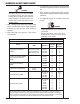
WARRANTY SCHEDULE 5 Years Parts* / 3 Years Labor ArcMaster, Excelarc, Fabricator, Fabstar, PowerMaster Portafeed, Ultrafeed, Ultima 150, WC 100B * 5 years on the Original Main Power Transformer and Inductors not mounted on PCBoards.
THE AMERICAS Denton, TX USA U.S.