
User guide


January 23, 2004 2 Manual 0-2856
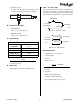
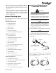
2. Machine Torches
Available with fiberglass mounting tube & rack
and phenolic (plastic) pinch block assembly.
A-02812
B. Torch Leads Lengths
• Hand Torches:
20 ft (6.1 m) or 50 ft (15.2 m)
• Machine Torches:
25 ft (7.6 m) or 50 ft (15.2 m)
C. Torch Ratings
Ambient
Temperature
104° F
(40° C)
Duty Cycle
100% @ 40 Amps @ 200 scfh
Maximum Current
40 Amps
Voltage (V
peak
)
500V
Arc Striking Voltage
12 kV
Torch Ratings
NOTE
Power Supply characteristics will determine ma-
terial thickness range.
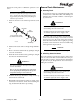
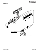
D. Torch Parts
Gas Distributor, Electrode, Tip, Shield Cup
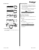
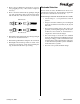
E. Parts - In - Place (PIP)
The torch head has built - in contacts called Parts - In
- Place (PIP). These two contacts are made through
the inside of the shield cup when it is installed. The
torch will fail to operate if these contacts are not made.
A-00458
Torch Switch
PIP Pin
PIP Pin
Shield Cup
To Control
Cable Wiring
PIP Circuit - Machine Torch
A-03540
Torch Trigger
PIP Pins
Shield Cup
To Control
Cable Wiring
Torch Switch
PIP Circuit - Hand Torch
F. Gas Requirement
1. Single Plasma / Secondary Gas
Compressed Air
2. Pressure
70 psi (4.8 bar)
CAUTION
Maximum input gas pressure must not exceed 125
psi (8.6 bar)
3. Total Flow
Cutting: 200 scfh (94.4 lpm)
Gouging: 230 scfh (108.5 lpm)
scfh = standard cubic feet per hour