
User guide

January 23, 2004 3 Manual 0-2856
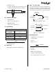
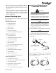
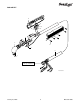
G. Dimensions
A-03024
7.98 in (203 mm)
2.95 in
(75 mm)
7.31 in (186 mm)
3.13 in
(80 mm)
10.5 in (266.7 mm)
3 in
(76.2 mm)
9.86 in (250.4 mm)
3.18 in
(80.8 mm)
1.4 in
(35.6 mm)
14.1 in (358 mm)
1.1 in
(27.9 mm)
0.6 in
(15.2 mm)
5.1 in
(130 mm)
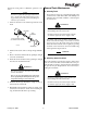
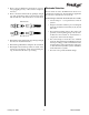
I. Direct Contact Hazard
For exposed tip the recommended standoff is 1/8" -
3/8" ( 3 - 9 mm).
Connecting Torch
1. Follow the instructions supplied with the appro-
priate Adapter Kit to connect the torch lead con-
nections to the Adapter Kit parts for connection
to the Power Supply.
2. Refer to Torch Parts Selection and check the torch
for proper parts assembly (see CAUTION).
CAUTION
The torch parts must correspond with the type of
operation. Refer to Torch Parts Selection.
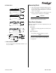
Torch Parts Selection
The type of operation to be done determines the torch
parts to be used.
Torch parts:
Shield Cup, Cutting Tip, Electrode and Gas Dis-
tributor
Type of operation:
Drag cutting, standoff cutting or gouging
NOTE
Refer to the section titled Torch Consumables for
the various torch parts that are used depending on
the application.