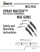
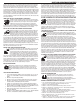
AIR-COOLED MIG GUN 250 AMP, 350 AMP, 450 AMP CURRENT WIRE SIZE DUTY CYCL E UP TO UP TO UP TO 450 AMPS 3/32" (2.4 mm) 80% SPRAY MASTER™ WITH VELOCITY CONSUMABLES MIG GUNS Safety and Operating Instructions IMPORTANT: Included inside - special instructions for NEW consumables. Revision: AA Issue Date: May 15, 2014 Manual No.: 89200016 Tweco.
WE APPRECIATE YOUR BUSINESS! Congratulations on receiving your new Tweco Spray Master™ product. We are proud to have you as our customer and will strive to provide you with the best service and support in the industry. This product is backed by our extensive warranty and world-wide service network. We know you take pride in your work and we feel privileged to provide you with this high performance product that will help you get the job done.
WARNING Read and understand this entire Manual and your employer’s safety practices before installing, operating, or servicing the equipment. While the information contained in this Manual represents the Manufacturer’s judgment, the Manufacturer assumes no liability for its use. Spray Master™ with Velocity MIG Guns Safety and Operating Instructions Instruction Guide Number 89200016 Published by: Victor Technologies, Inc. 2800 Airport Rd. Denton, TX. 76208 (940) 566-2000 www.Tweco.com U.S.
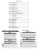
Table of Contents SECTION 1: SAFETY PRECAUTIONS...........................................................................2 Mesures de sécurité.......................................................................... 2 SECTION 2: INTRODUCTION.......................................................................................4 2.01 How to Use this Manual.................................................................... 4 2.02 Receipt of Equipment.........................................................
SAFETY AND OPERATING INSTRUCTIONS cylinders, chains, wires, ropes, cranes, and hoists away from any part of the electrical path. All ground connections must be checked periodically to determine if they are mechanically strong, and electrically adequate for the required current. When engaged in AC welding/ cutting under wet conditions or where perspiration is a factor, the use of automatic controls for reducing the no load voltage is recommended to reduce shock hazards.
SAFETY AND OPERATING INSTRUCTIONS SECTION 2: INTRODUCTION 2.01 SECTION 4: MIG GUN INSTALLATION NOTE Be certain that the end user (welder, operator, or helper) reads and understands these instructions. Be certain that the welder also reads Section 2 “Safety Precautions.” HOW TO USE THIS MANUAL To ensure safe operation, read the entire manual, including the chapters on safety instructions and warnings. Throughout this manual, the words WARNING, CAUTION, and NOTE may appear.
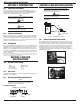
SAFETY AND OPERATING INSTRUCTIONS SECTION 5: SPRAY MASTER WITH VELOCITY MAINTENANCE This section discusses servicing and or replacing various components of the Spray Master MIG Gun. WARNING Disconnect power from MIG Gun before servicing. 5.01 INSTALLING OR REPLACING VELOCITY CONTACT TIP Avoid excessive consumables wear by periodically rotating tips. Increase consumables life by occasionally rotating tips.
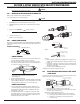
SAFETY AND OPERATING INSTRUCTIONS Lock Collar Spring Washer Spray Master Replacement Kit Parts List Snap Ring Description 4. 5. Slide the Stainless Steel Sleeve onto the conductor tube end. Align the set screw with the threaded hole in the conductor tube and tighten until the screw bottoms out. Do not overtighten. The conductor tube Stainless Steel Sleeve replacement is complete. Trim the conduit and install the consumables. 5.
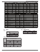
SAFETY AND OPERATING INSTRUCTIONS MEDIUM DUTY CONTACT TIPS Part No. Description VTM23 .023" (0.6 mm) VTM30 .030" (0.8 mm) VTM35 .035" (0.9 mm) VTM40 .040" (1.0 mm) VTM45 .045" (1.2 mm) VTMA364 * 3/64" (1.2 mm) VTM52 .052" (1.3 mm) VTM116 1/16" (1.6 mm) VTMA116 * 1/16" (1.6 mm) VTM564 5/64" (2.0 mm) HEAVY DUTY CONTACT TIPS Stock No. 1160-1750 1160-1751 1160-1752 1160-1753 1160-1754 1160-1755 1160-1756 1160-1757 1160-1758 1160-1759 Part No. Description VTH30 .030" (0.8 mm) VTH35 .035" (0.9 mm) VTH40 .
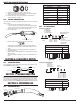
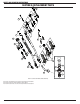
SAFETY AND OPERATING INSTRUCTIONS SECTION 9: REPLACEMENT PARTS 12a 12 11a 14 11 10a 10 13 13b 7 8 13a 7a 9b 9 9c 6 4 9a 3 2 5 1 Refer to Section 8 for Nozzles and Contact Tips Refer to 8.02 Tips and Nozzles for tip and nozzle part numbers and descriptions. Refer to 8.03 Conduit for conduit part numbers and descriptions. Refer to 8.04 Conductor Tube for conductor tube part numbers and descriptions.
SAFETY AND OPERATING INSTRUCTIONS Item No.
THE AMERICAS Denton, TX USA U.S.