Troubleshooting Ultracut & Autocut Systems from Status Codes This is work in progress, do not assume correct or complete The power supply for these systems is made by another company to TDCs specifications. The rest of the system, the Communications & Control Module (CCM), Remote Arc Starter (RAS), and various gas controls (GCM 1000, GCM 2000, GCM 2010) were designed and are manufactured by TDC.
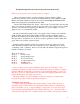
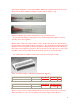
and crimp a small piece of steel wire, 0.020 to 0.025” dia. (0.5-0.6 mm) works best, into where wire would normally be crimped. A paper clip is a little too big. Insulate all but the end of wire and slide these onto your meter probe. If your meter has alligator clip adaptors you could hold the wire in these as well, be sure they don’t short together. Ribbon cable: There are 3 ribbon cables, 16 ckt., 26 ckt. and 34 ckt. For earlier units to measure ribbon cable signals requires test adaptors.
Digi-Key Part Number 922576-20-ND Price Break Unit Price Price 14.84000 14.84 1 Manufacturer Part Number 922576-20-I Digi-Key Part Number 922576-40-ND Price Break Unit Price Price 1 18.90000 18.90 Manufacturer Part Number 922576-40-I Power Supply Status Codes Group 1, Process Codes 1-1 E-Stop Activated or Plasma Enable Off Code 1-1 is activated by either an open circuit between TB1-1&2 (External EStop) on CCM I/O PCB or Plasma Enable switched off.
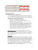
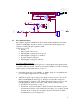
External E-Stop E-Stop input is on CCM module TB1-1&2. This circuit must be closed for normal operation; open activates E-Stop, generating 1-1 code. CCM is supplied from the factory with a jumper across TB1-1&2. The jumper may be replaced with an external switch for remote E-Stop. D21 (CNC E-Stop) on the CCM I/O PCB will light when TB1-1&2 is closed. If D21 is not on, problem is missing jumper, defective external E-Stop switch or its wiring or the CCM is defective.
J9 connects 1:1 to J54 HMI Power connector on rear panel of CCM J9 24 VAC 24 VAC 24 VAC RET 4 150 1N4004 1 24 VAC Power to HMI 1 2 3 4 5 6 Jumper in HMI PLASMA ENABLE 2 3 K6 100uF 63V 8 5 7 6 +15V K3 E_STOP CNC K5-E-STOP 2 6 + 5 1.2K E-STOP to GAS Control 1N4004 4 3 1 DPST D2 E-STOP to Power Supply E-STOP_ PS GREEN To CPU E-Stop Input 10 9 47K 1N4148 CD4050BC 0.1uF 1-2 75.
• If T1 measures OK, check for shorted capacitors C1-C3. 3. No 120 VAC to T1 primary during the ignition phase (15 seconds following Preflow) check for 120 VAC into the line filter. It it’s there replace the filter. If not present go to step 4. 4. CCM sends signal HF Enable (active low) at J35-10 to CN10-10 (other end of ribbon cable) on power supply board WK-5602 (PCB5). Signal leaves PCB5, still active low, on CN8-4 and goes to CN8-4 of relay board WK-5628 (PCB7) closing relay RY5.
For resistor pilot units where the pilot current is controlled by the main inverter, Pilot Enable causes PCB5 to connect Pilot Demand to the inverter signal I_REF. See section on Eagle 100-300 Demand Signals – Cutting & Pilot for troubleshooting. For Chopper Pilot units Pilot Demand is sent from CN33-3 (CN33-4 common) to CN2-3 chopper. See section on Eagle 100-300 Demand Signals – Cutting & Pilot for troubleshooting.
• 1-3 Pilot Out Pilot has ignited as sensed by Pilot On signal, but went out on its own before the timeout (85 ms. or 3 sec.). Possible causes: • Preflow pressure too high, check cut charts for proper setting. • • • • 1-4 charges a capacitor. If using a meter with a diode scale, expect to see continuity one way (diode forward biased) and open with probes reversed. A low resistance with either method indicates a short. Chopper IGBTs. Measure resistance TB1 to TB4 on chopper. Should be open circuit. .
Causes for 1-4 code: • Cut demand set much lower than recommended for torch parts, i.e. 100A consumables in torch but cut current set for 30 or 50A (or zero). Current may be too low to keep arc on. • Torch standoff too high for cutting process being used. • Preflow gas flow to low due to a leak somewhere between the preflow regulator and the torch? Check for leaks. • Remote analog current control switches set wrong.
1-5 Off the Plate (software not currently implemented) Off the Plate feature, when activated (CCM CPU board’s SW5-2 on), detects rapid rise in voltage when torch runs out of metal and cuts the arc off to prevent bending and stretching the arc too far which can damage the torch parts. Status code 1-5 is not a fault but instead indicates Off the Plate has functioned. 1-6 Transfer Timeout Pilot time is limited to either 85 ms.
• Blown fuse in wall fuse/disconnect box or phase missing from power distribution. • Loose connection on power cord. • C.P1 (On/Off SW) defective. • Shorted inrush SCR in inverter module input rectifier bridge. • Defective power supply PCB (PCB1, PCB4, PCB5) • Defective CCM Missing Phase The power supply checks for 3 phase voltage at both the power supply input terminals and at D1 (3 phase bridge on horizontal panel behind front panel) coming through C.P1 (front panel On/Off SW).
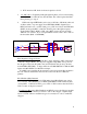
R2 + measure resistance between terminals marked R2 and +. Should measure be hundreds or thousands of ohms. A short will read less than 100 ohms. Power supply boards Look on PCB5, WK-5602A, for LED2, Missing Phase, illuminated brightly. When phase is not missing will still be on but not so bright. (Don’t blame me, I didn’t design it.) If not, problem is likely in the CCM but still could be in the output side of PCB5.
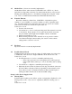
When a phase is not missing the optoisolator, PHC2, output transistor is off or open so voltage across CN7-1 & 2 is +15 VDC. When a phase is missing, the opto turns on for the time that VACIN is lower than 2.5 V making the output across CN7-1 & 2 into a string of low going pulses. PCB4 PCB5 +12VDC +15V 1 PHC2 CN7 4 VACIN 3 2 + 1 2 3 4 5 CN7 1 2 3 4 5 Pulse Detector When L1 phase is missing, the voltage measured across CN7-1 & 2 will be less than 15V, probably around 12 V.
2-2 Input voltage out of range. The Power supply contains circuits that monitor the AC input voltage. This works as wrong voltage detection i.e. if unit is configured for 208-230 and 460V is applied. If there is more than one inverter and one is configured wrong or the harness connecting to CN1 (230V) or CN2 (460V) on the voltage selection PCB in not connected it will signal wrong voltage, voltage out of range.
If code set just after arc transfer: • Unit pilots OK and can perhaps cut at lower currents but higher current will set 2-2 shortly after transfer. Wires to power supply or wires from fuse box to mains too small for the current cause voltage drop as current rises. Voltage will measure OK when not trying to cut. Poor Power Quality: • Voltage can go out of range momentarily from a few ms. to a couple seconds then recover. Inverter fans are powered from a DC supply.
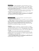
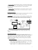
INVERTER MODULE MC1 VOLTAGE SELECT PCB JUMPERED FOR 230 JUMPERED FOR 400-600 D1 & 2 PCB1 D3 & 4 R1-10 PCB3 CN2 1 CN2 1 CN4 Voltage Level Detection Circuits VACIN PCB4 MISSING INPUT OUT PHASE OF RANGE CN7 5 4 3 Input_NG 5 PCB5 1 Part of D1 Bridge rectif ier 4 CN1 CP1 3 6 MISSING_PHASE 6 RY 3 CN7 PGND 2 3 5 2 3 1 2 2 R1 R11 1 D5 & 6 1 2 3 4 CN1 (CN2) 1 2 3 4 3 Phase AC +15V LED3 LED2 INPUT NG MISSING PHASE 1 PCB7 MC1 RY 1 RY 1 RY 1 TP0 RY2 RY 2 8 +15V
INPUT_NG is derived from VACIN which comes from PCB1 where the 3 phase input is rectified and divided (See section on Voltage Selection & Wrong Voltage Detection for full explanation of how VACIN is derived) and goes to CN2-1 on PCB3 where it is passed directly to PCB4 which is daughter board that plugs into PCB3. PCB1 VACIN can be measured at CN2-1 (+) and PGND CN2-2 (-) on PCB3 (WK5694). PGND can be accessed easiest at CN1-1 on PCB3. It is also present at CN2-2.
2-3 Power Supply Overheated. Inverter module(s) and pilot regulator (chopper) module have sensors monitoring their temperature. An over temperature in either inverter, chopper or torch coolant will turn on the front panel TEMP indicator however the torch coolant system over temperature sets a different code. Because the unit is 100% duty cycle it should never see an over temperature in normal operation.
If no or reduced flow, suspect failed fan. Fans can be inspected / replaced without removing inverters. At the rear of the unit there are removable panels to access the fans. Verify the suspected fan is not turning then shut off power, disconnect the fan connector, turn power back on and measure for 24 VDC at the connector. If voltage is present fan is defective. If no 24 VDC, inverter module is defective. Chopper (Pilot Regulator) Fan Chopper fan runs continuously whenever unit has power, no timeout.
Power Supply PCB PCB5, WK-5602A, takes the signal /TEMP_ERR from the inverters on CN614, combines it with signal CHOPPER_TEMP_ERR (units after early 2006) and inverts it becoming signal /TEMP OK which is sent to the CCM on CN11-8 (J368 on CCM). Signal is low when temperature is OK. If, with the ribbon cable disconnect from CN6 on PCB5 and the harness from the chopper (if present) disconnected from CN17, the signal on CN11-8 is not low PCB5 is defective. CCM Signal /TEMP OK on J36-8 is active low.
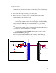
T 100A INVERTER MODULE # 1 (Top) CN2-460V N (-) V Change PCB S 4 2 2 1 1 3 3 P (+) 4 3 2 1 4 CN1-230V CN4 - PCB12 R 460 230 COM CN6 T 100A INVERTER MODULE # 2 (bottom) N (-) V Change PCB S 4 2 3 1 2 1 3 4 3 2 1 4 CN1-230V CN4 - PCB12 R CN6 P (+) 4 3 2 3 CN4 1 COM 230 2 CN2 1 460 COM_A 230_A 460_A CN2-460V RY6 +12VDC CN5 CN6 CN1 CN5 CN6 PCB4 + RY 2 CN4 WK-5604 DETECTOR PCB 230V RY5 5 4 3 2 CN7 1 1 CN3 2 +12VDC 2 CN10 FROM AC INPU
Measure for 110 VAC on contactor coil. If present and contactor is not energized then contactor is defective. If 110 VAC is not present, either PCB5 is bad or no 110 VAC from T1 transformer. PCB4 or PCB7 If unit has 2 or 3 inverters first determine which inverter is causing /READY TO OPERATE to be false. With two or three inverters you can disconnect ribbon cable from CN6 of one inverter at a time (other ones remain connected). When 2-4 code goes away that is the inverter signaling the fault.
Inverter The active low signal /READY TO OPERATE comes from PCB5 and is sent to the CCM on J36-13 (34 ckt ribbon cable). Signal INV_READY comes from the inverter(s) as an active high (open collector) on CN6-8 (16 ckt. ribbon) to PCB5, WK-5602A. Any inverter can pull the line low if it is not ready. On PCB5 the active high signal is inverted to become active low signal /READY TO OPERATE. /READY TO OPERATE is sent to the CCM on J36-13.
Code 2-5 remains set (latched) after Start is removed to indicate why unit stopped. Code is cleared next time Start is applied (if fault has been removed) or when power is turned off. Causes for 2-5 code set before pilot ignition: • J6 on CCM not connected (CCM connection to DC Output Voltage) or open connection. • CN1 & CN14 reversed on PCB5 • Shorted Pilot Regulator (chopper). • Inverter not getting Start signals (START & START2) from CCM. • Inverter defective.
difficult to detect on a meter as it is only low for about 150 ms. If J35-6 does not go low even momentarily but remains high at about +10 VDC, CCM is defective. Another way to test for START is to temporarily jumper J35-6 to TP1 (CCM) and apply CNC START. If inverter(s) come on, front panel DC LED on, no 2-5 code, then CCM is defective. Inverter Defective. A number of possible failures could cause no or low DC from the inverter. Shorted output diodes.
Cut Demand from CCM may be measured at TP13 on CCM I/O PCB (TP1 common) or J35-2. Before CNC START, Cut Demand is set to zero, if it is other than zero CCM is defective. After receiving CNC START and during preflow Cut demand is set to a lower starting level (varies with output current setting and MAX current capacity of the unit) generally between 0.5 to 3.5 volts. Upon arc transfer Cut Demand ramps up to cutting level with a MAX of 10 VDC if current is set to MAX output.
as I_REF. I_REF is sent to the inverter module(s) on CN6-2 (16 ckt ribbon cable). I_REF should be 80% of Cut Demand if unit is 100, 200 or 300A. If unit is 150A, I_REF is 60% of Cut Demand . For example, 150A power supply set for 100A out. Initial cut demand should 1.7V, I_REF at CN6-2 should be 1.7 * 0.6 =1V. If it had been a 100A unit set for 100A Cut Demand would be 2.6V and I_REF should be 2.6 * 0.8 = 2.1V. If this is not correct PCB5 is defective.
defective. Signal Inverter OCR is sent to CCM on J36-16. If CN6-12 is not low and J36-16 is low PCB5 is defective or the 34 ckt ribbon cable is shorted. CCM If J35-16 is not low but code 2-6 is still flashing then CCM is defective. 2-7 Unwanted Current As soon as CNC Start is on, the inverters are turned on and should be producing open circuit voltage (OCV). There should be no output current at this time because without pilot ignition there should be no path for current.
For troubleshooting code 2-7 with software prior to version 2.1 got to Troubleshooting Unwanted Current Faults and start the beginning. For troubleshooting code 2-7 with software version 2.1 or later got to Troubleshooting Unwanted Current Faults sections on PCB5 and CCM. 2-8 Unwanted Pilot Current Signal As soon as CNC Start is on, the inverters are turned on and should be producing open circuit voltage (OCV).
• • • • • Short between power supply negative output and earth ground. Defective or incorrectly installed user supplied equipment such as torch height controls that make connections to power supply output. Defective work current sensor. Defective PCB5 Defective CCM Troubleshooting Unwanted Current Faults (codes 2-7, 2-8, 2-9): 1.
considered outside the supply. If it still sets code 2-7, 2-8 or 2-9 problem is inside power supply or in user installed equipment. Shorts outside the power supply Reconnect the negative and/or pilot leads at the rear of the power supply. It’s highly unlikely to have short between the negative (Torch) cable and the Pilot cable or Work cable between the power supply and RAS.
the J6 connector. You cannot test this by disconnecting J6 or the black and blue wires as this will set the 2-5, DC Output Low code which gets set first. o User installed equipment. User Installed Equipment For user installed equipment to cause 2-7 code it would have to be connected on the output (to the rear) of the current sensors. To test, disconnect user equipment and apply CNC START. If code 2-7 is gone user equipment was defective or connected incorrectly.
Group 3, Gas Control Codes. Also refer to Gas Control Status Codes at the end of this section. 3-1 Gas Control Communication Fault No signal detected over the fiber optic link from the gas control. In the case where there are additional other than Gas Control connected to the CANBUS this code would indicate the Gas Control is having communication problems while the other CANBUS devises are OK. We don’t currently have any other devises on the CANBUS so it is more likely that code 5-1 will be what is set.
3-6 Invalid Current Control level from Gas Control Whe ncCM requests the output current setting Gas Control it returned a value outside the range available from the power supply. Most likely cause is a firmware incompatibility problem. Consult factory for latest firmware update. 3-7 Gas Control returns wrong command sequence. Firmware incompatibility. Consult factory for latest firmware update. 3-8 Mismatch between the CCM and gas control type. One is for Autocut while the other is an Ultracut.
When there is a communication error it will be displayed but once it has recovered the display will show what the error was by displaying: ^E4 – Low level CAN bus error where the CCM did not acknowledge receiving a message from the Gas Control. ^E5 – Low level CAN bus error where the bus is off. ^E6 – CAN bus communication (the fiber optic) has timed out.
is pin 5 of the ribbon cable. Common is also available on at TP0 on PCB5 or TP1 on CCM I/O PCB. No flow, either actual or failure to sense flow, is most likely to set code 4-4 unless something fails after power up purge. If flow sensor or PCB fails after purge, you normally would try recycling power so again it would set 4-4. Possible causes for low flow. • Coolant filter (internal or external) clogged. • Coolant supply or return hose twisted or pinched reducing flow.
Coolant not overheated but code 4-3 still set: • Coolant temperature sensor circuit open • PCB5 • CCM Failed fan – Check for 24 VDC at fan connector, if present replace fan. Open Coolant sensor – Temperature sensor has leads about a foot long with a connector which connects to a 2 wire harness going to PCB5 CN1. If either end is not connected gives 4-3 fault. Coolant sensor measures about 20-25K ohms at room temperature. Resistance reduces as temperature goes up.
Coolant actually flows (for 30 sec. until pump shut off due to not sensing flow): • Flow sensor disconnected or failed, see sect. code 4-2 for description of flow sensor operation. • PCB5 • CCM Damaged Coolant Tube Coolant tube includes a check valve at it’s upper end. When cartridge with consumables is not installed the spring loaded coolant tube is fully extended closing the check valve preventing coolant from leaking out.
Sensor disconnected – flow sensor comes with wire about 1 ft. long and a connector that connects to a 3 wire harness. This could be disconnected or CN13 where the harness connects to PCB5 could be disconnected. Defective Flow Sensor – If sensor is not putting out pulses it may be setting at either +5V or 0 V. Measure for +5V on CN13-1 (common is TP0 on PCB5 or TP1 on CCM) to confirm that the +5V supply is present. Then measure CN13-2.
5-1 CANBUS Failure to Acknowledge fault. • Gas control is GCM 1000 with Basic ID problem • CANBUS / Fiber optic problem GCM 1000 (also called a Basic Gas Control) does not use the CANBUS (fiber optic) communication. A jumper in the gas control connector J56 pins 8 & 9, gives the signal “Basic ID” telling the CCM not to expect any CANBUS.
The codes are as follows: "6-1" = CCM Analog Voltage Error "6-2" = CCM Analog to Digital Converter (ADC) or Digital to Analog Converter Error. "6-3" = Coolant Flow Circuit Error (Flow rate too high) "6-4" = CCM Data Memory Error.