
y


16
Input_NG
LED2
D3 & 4
CCM
INPUT
NG
MISSING
PHASE
MC1
RY1
D5 & 6
VOLTAGE SELECT PCB
CN2
6
1
2
3
CP1
TP0
CN1 (CN2)
1
2
3
4
R11
CN2
6
1
2
3
CN7
1
2
3
4
5
MISSING
PHASE
PCB7
R1
INPUT OUT
OF RANGE
+15V
PCB5
RY2
+15V
MISSING_PHASE
Part of D1 Bridge rectif ier
D1 & 2
K5 E-Stop
CN7
1
2
3
4
5
JUMPERED
FOR 230
MC1
VACIN
Voltage Level
Detection
Circuits
RY2
CN4
1
2
3
4
RY1
18
JUMPERED FOR
400-600
INVERTER MODULE
R1-10
PCB1
PCB4
PCB3
RY3
T1
BIAS TRANSFORMER PRIMARY
460
0
220
LED3
CN1
1
5
3 Phase AC
PGND
RY1
PCB5
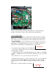
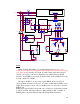
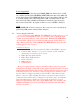
LED3 on PCB5, WK-5602A, is normally illuminated in any case. For a
couple seconds after power is applied it will be bright while system is performing
tests. After that if it remains very bright, problem is likely either that voltage is
actually out of range (or inverter configured wrong), PCB1 defective, PCB4
defective. If the LED3 is less bright, problem is likely in the CCM but still could
be in the output side of PCB5.
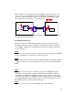
The input to PCB5 for wrong voltage signal, INPUT_NG is at CN7-4. It
should normally measure low, near zero V, relative to TP0, making LED3 on less
bright when voltage is correct. Also see PCB4 section for other ways to measure
INPUT_NG.
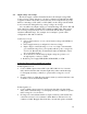
PCB5 places signal /Input Voltage OK (low) on CN11-15 (34 ckt ribbon) which
is J36-15 on CCM. (Measured relative to TP0 on PCB5 or TP1 on CCM). If
INPUT_NG is correct but /Input Voltage OK is high PCB5 is defective.