
Manual

TORCH DATA 8-28 Manual 0-4802 Rev. AJ
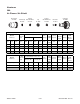
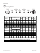
(ga) (in) inch (PSI) Ball (PSI) Ball (PSI) Volts
(in)
±0.005
(ipm) (in) (sec) (in)
3/8 0.375 40 67 120 62 120 152 0.154 60 0.350 0.2 0.105
1/2 0.500 40 67 120 62 120 158 0.150 50 0.350 0.2 0.110
5/8 0.625 40 67 120 62 120 160 0.150 35 0.350 0.5 0.110
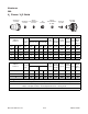
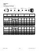
(Bar) Ball (Bar) Ball (Bar) Volts
(mm)
±0.1
(mm/min) (mm) (sec) (mm)
2.8 67 8.3 62 8.3 153 3.9 1490 8.9 0.2 2.7
2.8 67 8.3 62 8.3 157 3.8 1330 8.9 0.2 2.8
2.8 67 8.3 62 8.3 159 3.8 990 8.9 0.5 2.8
BOLD TYPE
indicates maximum piercing parameters.
Requires CCM version 3.4 or later. Requires GCM version 3.2 or later
(mm)
10
12
15
Pierce
Delay
Kerf Width
@ Rec.
Speed
Plasma
(H35)
Shield (N
2
)
Kerf Width
@ Rec.
Speed
Plasma
(H35)
Shield (N
2
)
Material
Thickness
Pre Flow
Pressure
(N
2
)
Cut Flow Rates /
Pressures
Arc
Voltage
Torch
Working
Height
Travel
Speed
Initial
Piercing
Height
Torch
Working
Height
Travel
Speed
Initial
Piercing
Height
Pierce
Delay
Material
Thickness
Pre Flow
Pressure
(N
2
)
C
ut Flow Rates
/
Pressures
Arc
Voltage
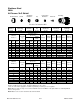
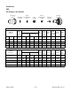
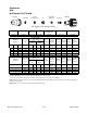
22-1041 22-1080 22-102022-1016 22-1036 22-1274 22-1062
Aluminum
100A
H35 Plasma / N
2
Shield
Shield Cup Shield Cap Shield Gas
Distributor
Tip Plasma Gas
Distributor
Electrode Cartridge
Shield
Gas Distributor
ElectrodeTipShield Cap
Shield Cup
This Graphic Is For Reference ONLY
Plasma Gas
Distributor
Art # A-08418
Cartridge