
User Manual

Manual 0-4731 Rev. AG 8-11 TORCH DATA
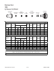
(ga) (in) inch (PSI) Ball (PSI) Ball (PSI) Volts
(in)
±0.005
(ipm) (in) (sec) (in)
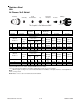
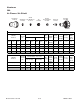
14 0.078 60 62 120 4 55 117 0.110 170 0.200 0.2 0.043
12 0.109 60 62 120 4 55 119 0.110 150 0.200 0.2 0.047
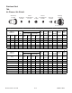
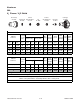
(Bar) Ball (Bar) Ball (Bar) Volts
(mm)
±0.1
(mm/min)
(mm) (sec) (mm)
4.1 62 8.3 4 3.8 117 2.8 4310 5.1 0.2 1.1
4.1 62 8.3 4 3.8 120 2.8 3660 5.1 0.2 1.2
* Pressure of the water supply line should be regulated by customer pressure regulator.
Note1:
Ohmic height sensing is not recommended with water shield. Water on the plate interferes electrically with the
ohmic sensing circuit.
Note2:
Water source used for shield must be demineralized.
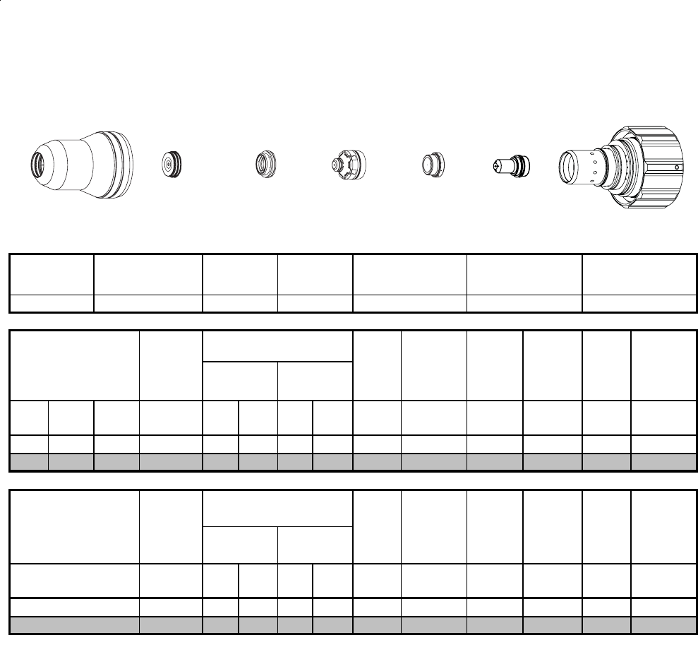
Stainless Steel
50A
N
2
Plasma / H
2
O Shield
Shield Cup Shield Cap Shield Gas
Distributor
Tip Plasma Gas
Distributor
Electrode Cartridge
22-1041 22-1078 22-102022-1016 22-1034 22-1274 22-1060
Material
Thickness
Pre Flow
Pressure
(N
2
)
Cut Flow Rates /
Pressures
Arc
Voltage
Torch
Working
Height
Travel
Speed
Initial
Piercing
Height
Pierce
Delay
Kerf Width
@ Rec.
Speed
Plasma
(N
2
)
Shield
(H
2
O)*
Material
Thickness
Pre Flow
Pressure
(N
2
)
Cut Flow Rates /
Pressures
Arc
Voltage
Torch
Working
Height
Travel
Speed
Initial
Piercing
Height
Pierce
Delay
Kerf Width
@ Rec.
Speed
Plasma
(N
2
)
Shield
(H
2
O)*
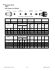
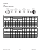
Requires CCM version 3.4 or later. Requires GCM version 3.2 or later
(mm)
2
3
BOLD TYPE
indicates maximum piercing parameters.
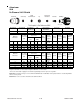
Shield
Gas Distributor
ElectrodeTipShield Cap
Shield Cup
This Graphic Is For Reference ONLY
Plasma Gas
Distributor
Art # A-08418
Cartridge