
User Manual

Torch Data 8-11 Manual 0-4821 Rev. AG
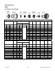
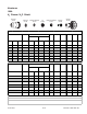
(ga) (in) inch (PSI) Ball (PSI) Ball (PSI) Volts
(in)
±0.005
(ipm ) (in) (s ec) (in)
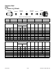
3/8 0.375 40 65 120 59 120 148 0.130 50 0.250 0.3 0.090
1/2 0.500 40 65 120 81 120 158 0.130 37 0.250 0.5 0.100
5/8 0.625 40 65 120 43 120 172 0.140 26 0.250 0.6 0.115
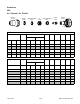
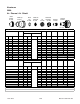
(Bar) Ball (Bar) Ball (Bar) Volts
(mm)
±0.1
( mm/min )
(mm) (sec) (mm )
2.8 65 8.2 59 8.2 149 3.3 1220 6.4 0.3 2.3
2.8 65 8.2 81 8.2 156 3.3 1010 6.4 0.5 2.5
2.8 6 5 8.2 43 8.2 168 3.5 7 40 6.4 0 .6 2.8
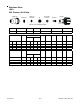
Stainless Steel
100A
H35 Plasma / N
2
Shield
S hield Cup S hiel d Cap S hield Gas
Distributor
Tip Plasma Gas
Dist ributor
Electrode Cartridge
35-1041 35-1080 35-102035-1016 35-1034 35-1274 35-1062
Materia l
Thicknes s
Pre Flow
Pressure
(N
2
)
Cut Flow Rates /
Pressures
Arc
Vo l ta g e
Torch
Wo rking
Height
Travel
Spe e d
Initial
Pie rcing
Height
Pierce
Delay
Kerf W idth
@ Rec.
Speed
Plasma
(H 35)
Shield (N
2
)
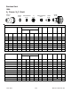
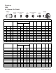
Materia l
Thicknes s
Pre Flow
Pressure
(N
2
)
Cut Flow Rates /
Pressures
Arc
Vo l ta g e
Torch
Wo rking
Height
Travel
Spe e d
Initial
Pie rcing
Height
Pierce
Delay
Kerf W idth
@ Rec.
Speed
Plasma
(H 35)
Shield (N
2
)
BOLD TY PE
indi cates maximum piercin g pa rameters.
Requires CCM version 3.4 or l ater. Requires GCM version 3.2 or l ater
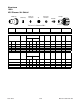
(mm)
10
12
15
Electrode
Shield Cap
Tip
Shield Gas
Distributor
Plasma Gas
Distributor
Cartridge
Shield Cup
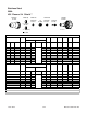
This Art Is For Reference ONLY
Art # A-07958_AB