
User Manual

Torch Data 8-12 Manual 0-4821 Rev. AG
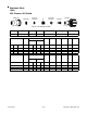
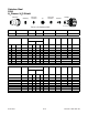
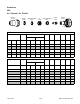
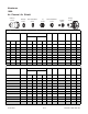
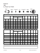
Stainless Steel
100A
N
2
Plasma / H
2
O Shield
(ga) (in) inch psi Ball* psi Ball* psi Volts
(in)
±0.005
(ipm) (in) (sec) (in)
10 0.141 80 60 120 5 55 156 0.125 160 0.200 0.000 0.074
3/16 0.188 80 60 120 5 55 158 0.125 100 0.250 0.300 0.080
1/4 0.250 80 60 120 5 55 16 5 0.125 60 0.250 0.300 0.086
3/8 0.375 80 60 120 5 55 17 3 0.125 50 0.250 0.300 0.087
1/2 0.500 80 60 120 5 55 17 9 0.130 35 0.300 0.500 0.100
5/8 0.625 80 60 120 5 55 18 1 0.140 30 0.300 0.600 0.110
3/4 0.750 80 60 120 5 55 185 0.150 25 0.120
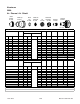
bar Ball* bar Ball* bar Volts
(mm)
±0.1
(mm/min) (mm) (sec) (mm)
5.5 60 8.3 5 3.8 155 3.2 4810 4.5 0 1.8
5.5 60 8.3 5 3.8 157 3.2 3530 5.5 0.1 1.9
5.5 60 8.3 5 3.8 159 3.2 2400 6.4 0.3 2.1
5.5 60 8.3 5 3.8 163 3.2 1750 6.4 0.3 2.2
5.5 60 8.3 5 3.8 169 3.2 1390 6.4 0.3 2.2
5.5 60 8.3 5 3.8 174 3.2 1210 6.5 0.3 2.3
5.5 60 8.3 5 3.8 178 3.3 970 7.3 0.5 2.5
5.5 60 8.3 5 3.8 180 3.5 800 7.6 0.6 2.7
5.5 60 8.3 5 3.8 186 3.9 600 3.0
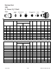
* B al l sett i ng for s hiel d wat er is s et usi ng c ustomer li ne pres sure of 55 ps i / 3. 8 bar
Bold type
indicates maximum piercing parameters.
Bold italic
i ndicat es edge s t art s only.
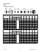
Edge Start
Kerf
Width
@ Rec.
Speed
Travel
Speed
Initial
Piercing
Height
Pierce
Delay
Kerf
Width
@ Rec.
Speed
5
15
20
6
8
10
12
(mm)
3
4
S hield ( H
2
O)
100A Stainless Steel (N
2
/H
2
O)
Ma te ri al
Thicknes s
Arc
Voltage
Torch
Working
Height
Travel
Speed
Initial
Piercing
Height
Pierce
Delay
Cut Flow Rates / Pres s ures
Plasma (N
2
) Shield (H
2
O)
NOTE:
Ohm i c height s ensi ng is not rec om m ended wi t h wat er s hi eld. Wat er on t he plat e i nt erferes
elect rical l y wi t h t he ohmi c sens i ng s ystem.
P re Flow
Pressure
(N
2
)
P re Flow
Pressure
(N
2
)
Ma te ri al
Thicknes s
Arc
Voltage
Torch
Working
Height
Edge Start
Cut Flow Rates / Pres s ures
Plasma (N
2
)
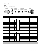
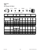
Electrode
35-1034
35-1272
35-1053
35-1041
35-1089
Cartridge
35-1020
Shield Cup
35-1016
Plasma Gas Distributor
Shield Gas Distributor
Tip
Shield Cap
Art # A-07297