
User Manual
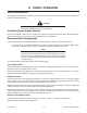

Torch Data 8-6 Manual 0-4821 Rev. AG
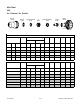
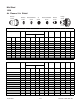
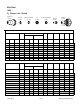
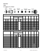
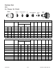
Mild Steel
100A
O
2
Plasma / Air Shield
(ga) (in) inch psi Ball psi Ball ps i Volts
(in)
±0.005
(ipm) (in) (sec) (in)
16 0.060 74 56 120 90 90 127 0.110 500 0.250 0.1 0.071
10 0.135 74 56 120 90 90 134 0.110 240 0.250 0.2 0.081
3/16 0.188 74 56 120 90 90 128 0.120 185 0.250 0.3 0.073
1/4 0.250 74 56 120 90 90 130 0.120 130 0.300 0.3 0.095
3/8 0.375 74 56 120 90 90 138 0.130 80 0.300 0.3 0.113
1/2 0.500 74 56 120 90 90 138 0.140 57 0.300 0.3 0.113
5/8 0.625 74 56 120 90 90 144 0.140 45 0.350 0.5 0.111
3/4 0.750 74 56 120 90 90 15 0 0.150 25 0.138
1 1.000 74 56 120 90 90 164 0.200 10 0.140
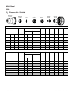
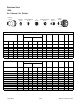
bar Ball bar Ball bar Volts
(mm)
±0.1
(mm/min) (mm) (sec) (mm)
5.1 56 8.3 90 6.2 129 2.8 11050 6.4 0.1 1.9
5.1 56 8.3 90 6.2 132 2.8 7580 6.4 0.2 2.0
5.1 56 8.3 90 6.2 131 2.9 5500 6.4 0.2 2.0
5.1 56 8.3 90 6.2 128 3.1 4500 6.5 0.3 1.9
5.1 56 8.3 90 6.2 130 3.1 3610 7.3 0.3 2.3
5.1 56 8.3 90 6.2 134 3.2 2640 7.6 0.3 2.7
5.1 56 8.3 90 6.2 138 3.3 1950 7.6 0.3 2.9
5.1 56 8.3 90 6.2 138 3.5 1580 7.6 0.3 2.9
5.1 56 8.3 90 6.2 142 3.6 1230 8.5 0.4 2.8
5.1 56 8.3 90 6.2 152 4.0 580 3.5
5.1 56 8.3 90 6.2 163 5.0 280 3.6
Bold type
i ndicat es maxi m um pierc i ng paramet ers .
Bold italic
indi c ates edge st art s only.
100A Mild Ste e l (O
2
/Air)
Ma te ri a l
Thicknes s
Arc
Voltag e
Torch
Working
Height
Travel
Speed
Initial
Piercing
Height
Pierce
Delay
Kerf
Width
@ Rec.
Speed
P r e Flow
Pressure
(Air)
3
Torch
Working
Height
Travel
Speed
Initial
Piercing
Height
(mm)
2
Ma te ri a l
Thicknes s
Arc
Voltag e
4
5
6
8
10
12
15
20 Edge Start
Edge Start25
Cut Flow Rates / Pres s ures
Plasma (O
2
) Shield (Air)
P r e Flow
Pressure
(Air)
Cut Flow Rates / Pres s ures
Plasma (O
2
) Shield (Air)
Edge Start
Edge Start
Kerf
Width
@ Rec.
Speed
Pierce
Delay
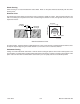
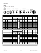
Cartridge
35-1020
Shield Cup
35-1016
Shield Cap
35-1027
Shield Gas Distributor
35-1272
Tip
35-1053
Plasma Gas Distributor
35-1041
Electrode
35-1071
Art # A-07291