
User Manual
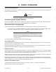

Torch Data 8-7 Manual 0-4821 Rev. AG
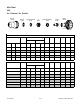
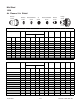
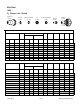
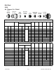
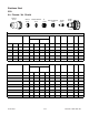
Mild Steel
200A
Air Plasma / Air Shield
(ga) (in) i nch p si Ball psi Ball p si Vol ts
(in)
±0.005
(ipm) (in) (sec) (in)
1/4 0.250 80 60 90 90 163 0.140 185 0.300 0 0.096
3/8 0.375
80 60
90 90 160 0.140 130 0.300 0 .1 0.131
1/2 0.500
80 60 90 90 162 0.140 100 0.300 0.3 0.150
5/8 0.625
80 60 90 90 164 0.140 75 0.300 0.4 0.158
3/4 0.750
80 60 90 90 168 0.180 60 0.350 0.5 0.176
1 1.000
80 60 90 90 177 0.200 35 0.500 1.5 0.189
1 1/ 4 1. 250 80 60 90 90 185 0.250 20 0.209
1 1/ 2 1. 500
80 60
90 90 189 0.250 15 0.225
22.000
80 60 90 90 204 0.300 10 0.270
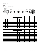
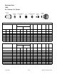
bar Ball bar Ball bar Volts
(mm)
±0.1
(mm/min) (mm) (sec) (mm)
5.5 85 6.2 6.2 163 3.6 4700 7.6 0 2.4
5.5 85 6.2 6.2 161 3.6 3970 7.6 0.1 2.9
5.5 85 6.2 6.2 160 3.6 3190 7.6 0.1 3.4
5.5 85 6.2 6.2 162 3.6 2710 7.6 0.3 3.7
5.5 85 6.2 6.2 163 3.6 2080 7.6 0.4 4.0
5.5 85 6.2 6.2 169 4.6 1430 9.5 0.6 4.5
5.5 85 6.2 6.2 176 5.0 920 12.5 1.4 4.8
5.5 85 6.2 6.2 185 6.4 500 5.3
5.5 85 6.2 6.2 189 6.4 380 5.7
5.5 85 6.2 6.2 196 6.9 320 6.2
5.5 85 6.2 6.2 203 7.5 260 6.8
Bold italic
type indicates edge starts only.
Edge Start50
8
10
See
Note
NOTE:
S e t ai r shi e l d pa ram eters by pressure o nl y.
25
38
44
32
15
20
See
Note
Arc
Voltage
Torch
Working
Height
(mm)
Travel
Speed
Initial
Piercing
Height
Edge Start
Kerf
Width
@ Rec.
Speed
Travel
Speed
Initial
Piercing
Height
Edge Start
Edge Start
Pierce
Delay
Edge Start
P r e Flow
Pressure
(Air)
Ma te ri al
Thicknes s
Plasma (Air)
12
Cut Flow Rates / Pres sures
Edge Start
Edge Start
Shield (Air)
6
200A Mild Ste e l (Air/Air)
P r e Flow
Pressure
(Air)
Cut Flow Rates / Pres sures
Plasma (Air) Shield (Air)
Pierce
Delay
Kerf
Width
@ Rec.
Speed
Ma te ri al
Thicknes s
Arc
Voltage
Torch
Working
Height
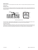
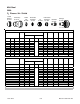
35-1018
35-1019
35-1028
35-1280
35-1055
35-1085
35-1020
Shield
Retainer
Shield Cup
Shield
Cap
Shield Gas
Distributor
Tip
Plasma Gas
Distributor
Electrode
Cartridge
Art # A-07292
35-1041