
Instruction Manual

1 Twin City Engineering Supplement ES-494
Removing Old Cone or Vane
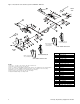
See Figure 2 for identification of all items referenced.
1. Shut off fan and lock out electrical power.
2. Remove belt guard and/or inlet screens.
3. Adjust motor position and remove belts and drive
sheave.
4. Clean and remove rust from sections of fan shaft
which extend through the fan bearings. File smooth
any burrs. Remove bearing bolts and raise the shaft
enough to take weight off the bearing.
5. Working through fan outlet or through access door,
block under periphery of fan wheel so that fan
housing supports the fan wheel.
6a. For Fan With Setscrew Locking Collars — Loosen
setscrews in bearing. Using wedges or pry bars,
slide bearing off end of shaft. If it is necessary to
force bearing, use a brass rod to drive against inner
race of bearing only.
6b. For Fans With Split Type Bearing — Remove bearing
cap, bearing housing and bearing insert off end of
shaft. If the bearing insert must be removed by
inexperienced personnel, it is recommended that the
bearing manufacturer be contacted to provide
instructions for dismounting.
7a. For Old Inlet Funnel Removal — Loosen fasteners
which hold inlet cone and bearing support frame to
the housing side. Remove old inlet cone and bear-
ing support frame.
7b. For Pre-1981 Style Inlet Vane Removal — Remove
hardware from old vane which attaches it to the
housing side. Remove control arm (or drive link).
Loosen fasteners which hold inlet cone and bearing
support frame to fan housing side, then remove old
inlet vane and bearing support frame.
7c. For Post-1981 Style Inlet Vane Removal — Remove
nut (item 16) and pull connecting arm out of the
way. Loosen fasteners which hold inlet vane and
bearing support frame to the housing side, then
remove the inlet vane and bearing support frame.
8. Repeat steps 4, 6, and 7 on other side of the fan.
Assembling Nested Inlet Vane
1. Using Figure 2 as a guide, assemble items 4
through 16 to the inlet vane. Measure threaded link-
age rod (item 6) to fit.
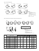
2. Center inlet vane in location of old vane or cone,
and rotate until inlet vane control ring is approxi-
mately in the same position as shown in Figure 3.
If old control linkage is being reused, locate control
ring clip so that connecting link can be reattached.
Be sure that when vane is partially closed the enter-
ing air will be spun in the direction of wheel rota-
tion.
3. For installation of new quadrant, using the dimen-
sions in Figure 4, position quadrant (item 2 or 2A)
to the housing side. Weld quadrant to the housing
frame (or housing side).
4. Drill a hole in the fan housing side to match the
diameter of control rod (item 3).
5. Reassemble bearing support frame and bolt it to fan
housing as shown in Figure 1.
6. Reassemble the bearing.
7. Repeat steps 1, 2, 4, 5, and 6 on the other side
of the fan.
8. Remove blocking under the fan wheel and check to
be sure the wheel turns freely. Adjust bearing posi-
tion or inlet vane position as required. Tighten bear-
ing fasteners.
9. Assemble the remaining parts of control system
according to Figure 2. Adjust position of connecting
links as required to enable both vanes to open/close
smoothly and uniformly. Threaded linkage rods (item
6) may have to be cut to required length.
10. Welded threaded linkage rod housing to hex nuts
(item 14). Spot weld the control rod to vane handle
and control linkage bar.
11. Reinstall the drive, guards, inlet screens, access
door hardware, etc.
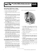
Figure 1. BC, BAF DWDI Fan With Nested Inlet Vanes
©2004 Twin City Fan & Blower
ES-494
May 2004
BC, BAF DWDI Nestled Inlet Vanes
INSTALLATION, OPERATION & MAINTENANCE MANUAL