
Manual


2 Twin City Engineering Supplement ES-995
of the foundation, approximately 1 to 1
1
⁄2" height should be
allowed for shimming, grouting, leveling, washers, nuts, etc.
Fans mounted on a sub-floor or mezzanine must have
adequate stiffness or be mounted on an inertia base with
springs properly selected.
If a structural steel base or platform is to be used, the
structure must be designed for the weight of the fan, live loads
imposed by rotation of the rotor and driver, and any external
live loads. The structure should be designed to ensure that no
natural frequency will occur within 30% of the fan speed. This
is especially true if the structure supports more than one fan.
Any ducting should have independent support. Do not use
the fan to support ducting as the housing or pedestal may
become distorted. The fan frame can be designed to carry
some external loads. Consult the factory if this is a concern.
Isolating the fan from ductwork with flex connections eliminates
transmission of vibration. Fans handling hot gases require
expansion joints at both the inlet and discharge to prevent
excessive loads caused by thermal growth.
Fan Installation, Factory Assembled Units
Follow proper handling instructions as given earlier.
1. Move the fan to the final mounting position.
2. Remove skid, crates and packing materials carefully.
3. If vibration isolation is to be used, place isolation base
on mounting bolts. Line up holes in fan base with bolts.
4. Place the fan on mounting structure. Carefully level the
unit (checking the level on the shaft) on the foundation
and shim as necessary using stainless steel shims on both
sides of each anchor bolt. Be careful not to force the fan
to the mounting structure/foundation. This may cause the
bearings to become misaligned or pinched causing vibra-
tion and premature failure.
5. Check the alignment of the bearings. Shim or reposition
the bearings if necessary.
6. Check face alignment of sheaves on belt driven fans.
Check tension of belts to see if it is sufficient. Sheaves
on belt driven fans are often provided with taperlock
bushings. When tightening bushing bolts, proceed in a
progressive manner to avoid cocking the tapered surfaces
between the bushing and the sheave.
7. Check alignment of factory mounted couplings, as they
are subject to misalignment during shipment and installa-
tion. Realign to within 0.002" offset and parallel. Allow for
thermal growth of the motor by setting the motor 0.001"
low for each inch of shaft up to 0.005". NOTE: Most
couplings need lubrication.
8. Check the tightness of the wheel on the shaft. Check the
tightness of foundation bolts, motor bolts, sheaves, and
bearings. Make sure there is no rubbing or binding and
that the wheel-inlet cone clearances and overlap are cor-
rect.
9. Check that bearings are fully lubricated and check the
oil level in the static oil lube systems. For spherical roller
bearings with split pillow block housings, the bottom half
of the housings should be 1/3 full of grease. For oil lube
bearings, the oil level should submerge the bottom-most
roller halfway into the oil.
10. Install any accessories shipped loose from the factory.
Fan Installation – Disassembled Units With
Split Housings
A unit is considered “disassembled” if any component required
for proper operation is shipped or supplied separately or in
pieces. Reference earlier instructions concerning proper han-
dling of fan components.
All units where assembly of the fan housing or bearing
pedestal or drive stand is required will have tags attached on
adjacent parts. These tags are used to identify which compo-
nents are joined together. Units which require extensive assem-
bly may require additional instructions located in the appendix.
Special instructions for some components and accessories are
also in the appendix.
1. Move the lower half of the housing to its mounting location.
2. Remove skids, crates, and packing materials carefully.
3. If vibration isolation is to be used, place the vibration iso-
lation base on mounting bolts. Line up holes in fan base
with bolts.
4. Place the lower housing on the mounting structure.
Carefully level the lower housing on the foundation and
shim as necessary using stainless steel shims on both
sides of each anchor bolt.
5. If the bearing pedestal(s) are separated they should be
installed next.
a. Move bearing pedestal(s) to mounting location.
b. Put vibration base, if any, in place. Set pedestal(s) on bolt(s).
c. Do not distort bearing pedestal by forcing it to align
with a non-level foundation. Shim beneath the pedestal
as necessary.
d. Check the bearing centerline height. Adjust the height
to match centerline height of the housing. High tem-
perature units may require a lower housing centerline
when cold so that it will be centered when hot.
e. Bring the bearing pedestal into square with the housing
using careful measurements or a large square.
f. Bolt the pedestal into position.
6. If the wheel and shaft were shipped unassembled, you
must now install the shaft in the wheel.
a. First use solvent to clean the protective coating off the
shaft. Check all surfaces for corrosion or nicks and
clean if necessary with fine emery cloth or a stone.
After thoroughly cleaning the shaft with solvent, do not
touch it with bare hands as perspiration can cause rust
or pitting over time.
b. Remove keys from the shaft.
c. Clean the inside of the wheel bore with solvent. Make
sure the setscrews will not interfere when inserting the
shaft into the wheel bore.
d. Insert the shaft into the wheel from the back side of
the wheel.
e. When the shaft is flush with the wheel hub (Arr. 1, 9
and 8), put the key into the keyway and tighten the
wheel setscrews.
f. Check the assembly drawing to make sure that the
wheel and shaft have been assembled correctly.
7. The rotor can now be installed in the housing. Slide the
bearings on if they are solid pillow blocks or loosely
mount the bottom halves if they are split. Inlet vanes and/
or inlet funnels may need to be installed over the shaft
before installing and bolting the bearings to their supports
(Arr. 3 and 7). Refer to steps 8 and 9 below for order
of assembly of components for double width and single
width fans. The shaft should be cleaned and oiled where it
will contact the bearings. Carefully lower the shaft assem-
bly into the bearings. Use care when lowering the shaft
onto the bearings so thrust bearings, collars, and liners
are not damaged due to misalignment. The bearing hous-
ing should be parallel to the axis of the shaft to prevent
loads caused by misalignment. Precision shim bearings
as required. Lock bearings. Be sure expansion bearing (if
supplied) is set to allow for growth.
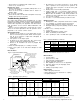
8. Arrangement 3 (split-housed) units (see Figure 1):
a. Parts on a DWDI unit are assembled in the following
order as viewed from opposite drive side: bearing bar
assembly and opposite bearing, funnel (housing side),
wheel (housing side), funnel, drive side bearing bar
assembly, drive bearing and sheaves. Mount bearing
bar assembly to housing. Center wheel in funnels.
b. Assemble parts in above order on shaft.
c. Proceed with connection of the shaft assembly to sup-
ports in step 7 above.
9. Parts on a SWSI unit are assembled in the following
order as viewed from opposite drive side: bearing bar
assembly and opposite bearing, funnel (housing side),
wheel (housing side), drive side bearing bar assembly,