
Manual


3 Twin City Engineering Supplement ES-995
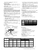
drive bearing and sheaves. Mount bearing bar assembly
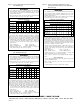
to housing. See Figure 2 for wheel-funnel overlap.
a. Assemble parts in above order on shaft.
b. Proceed with connection of the shaft assembly to sup-
ports in step 7 above.
10. Install motor on the base if applicable. Carefully align
shafts for drive installation.
11. Fans that have motors and drives mounted at the factory
are trim balanced prior to shipment. This is not possible
on units that are shipped without motors and drives.
The addition of drive components in the field can create
unbalance forces. Twin City Fan & Blower recommends
final balancing of the unit after the drive components
are installed. Failure to do so voids the Twin City Fan &
Blower warranty.
Bearing Installation
The following section gives some general instructions on bear-
ing installation. If bearings are to be field installed, the specific
installation manual for the bearings will be provided and should
be followed carefully. Always make sure to check the assembly
drawings and bearing manufacturer's instructions for location
of the fixed and expansion bearings. The positions of these
bearings cannot be interchanged.
Sleeve Bearings
1. The bearings should be disassembled and cleaned with
appropriate solvent, taking care not to interchange parts
between bearings. Parts of one bearing are generally not
interchangeable with parts from another bearing.
2. The lower bearing housing should be bolted loosely to
the pedestal. The lower liner should then be placed in the
housing.
3. Oil the lower liner per manufacturer’s instructions and
carefully sling the rotor assembly into place, being very
careful not to damage the bearing liners.
4. Make sure to install the oil slinger rings in their correct
location and peen the ring screws in place.
5. When handling the liners, be careful not to damage the
surfaces, as they are babbitted and are fragile.
6. The housings are generally tapped with a number of ports.
Be sure the oil level gauge, circulating oil supply and
discharge, thermocouples, etc., are correctly connected.
7. Make sure that proper oil type and quantity is used.
8. Make sure that the thrust collar screws, liner screws, cap
bolts, and plunger are torqued to manufacturer’s specifica-
tions.
Spherical Roller Bearings with Split Pillow Block Housings
1. The bearings should be disassembled, taking care not to
interchange parts between bearings. Parts of one bearing
Motor
Pedestal
Housing
Support Stand
(Housing Frame)
Wheel/
Impeller
Inlet
Funnel
Figure 1. Exploded View of Arrangement 4, SWSI Fan
Components
RBO, RBR Wheel Placement
Size
913 915 917 919 921 923 926 929 933 937 941 945 949 954 960
B
0.53 0.53 0.59 0.69 0.78 0.88 0.97 1.03 1.22 1.38 1.56 1.69 1.81 1.88 2.16
A
DIA
B
RBO RBR
BB
Figure 2. Wheel Placement (Wheel Overlap)
HIB, RTF Wheel Placement
Size
A B Size A B
180
20.50 0.31
400
45.25 0.69
200
22.50 0.34
450
50.00 0.75
220
25.00 0.38
490
55.13 0.81
240
27.50 0.44
540
61.00 0.91
270
30.38 0.47
600
67.50 1.00
300
33.50 0.50
660
74.25 1.13
330
37.00 0.56
730
82.00 1.22
360
41.00 0.63
800
90.75 1.34
HIB, RTF, HRT, HAF, BC, BCS, BAF, BAE
BC-SW, BC-DW, BCS, BAF SWSI & DWDI Wheel Placement
Size
122 135 150 165 182 200 222 245 270 300 330
A
12.25 13.50 15.00 16.50 18.25 20.00 22.25 24.50 27.00 30.00 33.00
B
0.32 0.34 0.38 0.44 0.56 0.63 0.69 0.75 0.88 0.97 1.06
RBA, RBO, RBR, RBP & RBW
Size
365 402 445 490 542 600 660 730 807 890
A
36.50 40.25 44.50 49.00 54.25 60.00 66.00 73.00 80.75 89.00
B
0.94 1.03 1.13 1.25 1.38 1.56 1.69 1.88 2.09 2.28
BAE SWSI & DWDI Wheel Placement
Size
182 200 222 245 270 300 330 365 402 445 490
A
19.00 20.82 23.16 25.51 28.11 31.23 34.36 38.00 41.90 46.33 51.01
B
0.38 0.41 0.46 0.50 0.55 0.62 0.68 0.75 0.83 0.91 1.01
Size
542 600 660 730 807
A
56.48 62.47 68.71 76.00 84.07
B
1.11 1.23 1.36 1.50 1.66
BAE SWSI & DWDI Wheel Placement
Size
122 135 150 165
A
12.25 13.50 15.00 16.50
B
0.31 0.34 0.38 0.44
A
RBA
RBA Wheel Placement
Size
907 909 911 913 915 917 919 921 923 926 929 933 937 941 945 949 954 960
A
0.25 0.38 0.47 0.53 0.59 0.69 0.69 0.0 0.0 0.0 0.0 0.0 0.0 0.0 0.0 0.0 0.0 0.0
MBW, MBO & MBR
MBW, MBO, MBR Wheel Placement
Size
196 224 252 280 308 336 365 421 477 533 589
MBW
0.50 0.44 0.38 0.25 0.38 0.44 0.56 0.63 0.75 0.75 0.88
MBO
0.50 0.44 0.38 0.25 0.38 0.44 0.56 0.63 0.75 0.75 0.88
MBR
0.25 0.25 0.25 0.25 0.25 0.25 0.38 0.56 0.69 0.81 0.94
GAP
B
A
Dia.
BCN Wheel Placement
Size
270 300 330 365 402 445 490 542 600 660 730
A
27.00 30.00 33.00 36.50 40.25 44.50 49.00 54.25 60.00 66.00 73.00
B
0.09 0.09 0.13 0.13 0.13 0.16 0.16 0.19 0.22 0.22 0.25
BCN
Note: On sizes RBO and RBR 905-911 wheel is to be centered in housing.
*For HAF overlap dimensions, consult Twin City
Fan & Blower.
Note: On sizes 421-589 wheel is to be centered in housing.
HRT Wheel Placement
Size
A
B
(Design 19)
B
(Design 23)
270
27.00 0.50 0.50
300
30.00 0.69 0.69
330
33.00 0.69 0.69
360
36.50 0.81 0.81
400
40.25 1.03 0.97
450
44.50 1.13 1.06
490
49.00 1.25 1.13
540
54.25 1.38 1.25
600
60.00 1.31 1.31
660
66.00 1.56 1.44
730
73.00 1.75 1.63
800
80.75 1.06 1.31
HAF Wheel Placement
Size
A B
220
240
270
300
330
360
400
450
490
540
600
660
730
800