
Manual


7 Twin City Engineering Supplement ES-995
□
Check rotation for agreement with rotation arrow.
□
Listen for any unusual noise.
Run unit up to speed:
□
Bearing temperatures are acceptable (<200°F) after one to
two hours of operation.
□
Check for excess levels of vibration. Refer to Table 1 for
vibration limits.
After one week of operation:
□
Check all nuts, bolts and setscrews and tighten if necessary.
□
Readjust drive tension if necessary.
Troubleshooting Guidelines
Use current safety practices when investigating fan or system
performance problems. General safe practices and performance
troubleshooting guidelines can be found in AMCA Publications
410 and 202, respectively. Fan application and field measure-
ment procedures can be found in AMCA Publications 201
and 203.
Below is a list of possible areas to check when air or sound
values do not match expectations. Most fan problems can be
pinpointed to one of these common causes.
Air Capacity Problems
1. Resistance of the system is not at design rating. If resis-
tance is lower than expected, both airflow and horsepower
may be up. If resistance is higher than anticipated, air
volume will be down.
2. Fan speed is not at design speed.
3. Air density is not at the design value. Also check air per-
formance measurement techniques/procedures.
4. Devices for air modulation are closed or plugged. Also
check filters.
5. Wheel mounted improperly or is rotating in reverse.
6. Parts of the system or fan have been damaged or need
cleaning.
Noise Problems
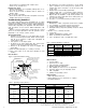
Temporary Form For
Grout Pouring
Hex Nut, Split Ring
Lock Washer, and
Tapered or Flat Washer
1" to 1.5"
Grout Allowance
To Be Filled With
Nonshrinking
Machinery Grout
Pipe-Bolt Sleeve
Dia. 2 to 2
1
/2 Times
Bolt Dia. For Correction
of Alignment Errors
Care Should Be Taken
That Anchor Bolt Sleeves
Are Filled With Grout
J-Bolt Leg Should Be
Fastened To Foundation
Rebar
Full Width Stainless
Steel Shims
Shimming Surface To Be
Smooth, Level, Dressed
If Necessary
Leveling Nut, If Used, Should Be
Backed Off After Shimming For
Final Tightening of Hex Nuts
Fan Base Angle
or Structural Steel
Figure 4. Typical Foundation Section
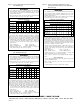
Condition
Fan
Application
Category
Rigidly Mounted
mm/s (in./s)
Flexibly Mounted
mm/s (in./s)
Start-up
BV-3 6.4 (0.25) 8.8 (0.35)
BV-4 4.1 (0.16) 6.4 (0.25)
Alarm
BV-3 10.2 (0.40) 16.5 (0.65)
BV-4 6.4 (0.25) 10.2 (0.40)
Shutdown
BV-3 12.7 (0.50) 17.8 (0.70)
BV-4 10.2 (0.40) 15.2 (0.60)
Table 1. Vibration Guidelines, unfiltered
Value shown are peak velocity, mm/s (inches/s), Filter out.
Table taken from ANSI/AMCA Standard 204-05, Table 6.3.
Table 2. Tightening Torque (Ft.-Lbs.)
Tolerance: /
-
5% The above torque values are for nonlubricated fasteners and Browning Bushings.
For wheel setscrews use Grade 2 values. For bearing setscrews, use manufacturer’s recommendations.
If other bushings are used, utilize bushing manufacturer's specifications.
+
1. Air performance is incorrect and the fan is not at design
point of operation. Fan is being forced to operate in an
unstable flow region near peak or to the left of the peak
of the curve.
2. Bearing failure. Check bearings (lubrication).
3. Supply voltage high or inconsistent supply frequency.
Adjustable frequency controllers can generate motor noise.
4. Objects which are installed in a high velocity airstream can
generate noise. This includes flow sensors, turning vanes, etc.
5. Poor fan inlet conditions.
6. Acoustics or sound measurement procedure incorrect.
Vibration Problems
1. Misalignment of drive components. Check belt or coupling.
2. Poor foundation or mounting structure (resonances).
3. Foreign material attached to rotating components.
4. Damaged rotating components (bearings, shaft, fan, wheel,
sheaves).
5. Broken, loose, or missing setscrews.
6. Loose bolts.
7. Vibration transmitted by another source.
8. Water accumulating in airfoil blades.
9. Fan is operating in stall or unstable flow region.
Motor Problems
1. Incorrect wiring.
2. Speed of fan too high.
3. Parts improperly installed; binding.
4. Bearings improperly lubricated.
5. WR
2
capability of motor too low for application.
6. Protection devices may be improperly sized.
7. VFD compatible.
8. Cabling and grounding correct.
Drive Problems
1. Belts improperly tensioned.
2. Drive alignment is poor. Check belt or coupling.
3. Coupling lubrication.
SIZE
FASTENER TAPER BUSHINGS
GRADE 2 GRADE 5 GRADE 8
SPLIT
QD
FOR DRIVE
IN IRON IN ALUM. HUB
#10 — — — — — 6
1
⁄4-20 5.5 8 12 7.9 7.5 9
5
⁄16-18 11 17 25 16 13 15
3
⁄8-16 22 30 45 29 24 30
7
⁄16-14 30 50 70 — — —
1
⁄2-13 55 75 110 70 — 60
9
⁄16-12 — — — — — 75
5
⁄8-11 100 150 200 140 112 135
3
⁄4-10 170 270 380 — — —
7
⁄8-9 165 430 600 — — —
1-8 250 645 900 — — —
1
1
⁄4-7 500 1120 1500 — — —