Transport GX21 B5102 1 2 3 1 2 RST User’s Manual Document Part Number: D1576-100
ii
PREFACE Copyright This publication, including all photographs, illustrations, and software, is protected under international copyright laws, with all rights reserved. Neither this manual, nor any material contained herein, may be reproduced without written consent of the manufacturer-. Copyright 2003-4 Version 1.0 Disclaimer Information contained in this document is furnished by TYAN Computer Corporation and has been reviewed for accuracy and reliability prior to printing.
Federal Communications Commission (FCC) Notice for the USA Compliance Information Statement (Declaration of Conformity Procedure) DoC FCC Part 15: This device complies with part 15 of the FCC Rules Operation is subject to the following conditions: 1) This device may not cause harmful interference, and 2) This device must accept any interference received including interference that may cause undesired operation.
About this Manual This manual provides you with instructions on installing your Transport GX21, and consists of the following sections: Chapter 1: Provides an Introduction to the Transport GX21B5102 bare-bones, packing list, describes the external components, gives a table of key components, and provides block diagrams of the system. Chapter 2: Covers procedures on installing the CPU, memory modules, an optional PCI card, and hard drives.
SAFETY INFORMATION Before installing and using the Transport GX21, take note of the following precautions: – Read all instructions carefully. – Do not place the unit on an unstable surface, cart, or stand. – Do not block the slots and opening on the unit, which are provided for ventilation. – Only use the power source indicated on the marking label. If you are not sure, contact the Power Company.
Table of Contents Chapter 1:Overview 1.1 1.2 1.3 1.4 1.5 About the Transport GX21 B5102 . . . . . . . . . . . . . . . . . . . . . . . . . 1 System Requirements . . . . . . . . . . . . . . . . . . . . . . . . . . . . . . . . . . . 1 Features . . . . . . . . . . . . . . . . . . . . . . . . . . . . . . . . . . . . . . . . . . . . . . 2 Unpacking . . . . . . . . . . . . . . . . . . . . . . . . . . . . . . . . . . . . . . . . . . . . 3 1.4.1 Box Contents (B5102G21S2H and B5102G21S2) . . . . . . . 3 1.4.
3.4.2 Disconnecting Cables . . . . . . . . . . . . . . . . . . . . . . . . . . . . 36 3.4.3 Removing the Motherboard . . . . . . . . . . . . . . . . . . . . . . . . 38 3.5 Replacing the CD-ROM/FDD. . . . . . . . . . . . . . . . . . . . . . . . . . . . 39 3.6 Replacing the FDD with a HDD . . . . . . . . . . . . . . . . . . . . . . . . . . 41 3.7 Replacing the LED Control Board . . . . . . . . . . . . . . . . . . . . . . . . 43 3.8 Replacing the S-ATA Backplane . . . . . . . . . . . . . . . . . . . . . . . .
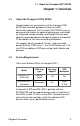
1.1 About the Transport GX21 B5102 Chapter 1: Overview 1.1 About the Transport GX21 B5102 Congratulations on your purchase of the Transport GX21 B5102 rack mounted, barebone system for Intel® Pentium® 4 processor. The Transport GX21 B5102 uses an advanced Intel chipset for optimum performance and reliability. Integrated storage contoller and Gigabit Ethernet ports combine to provide powerful computing capacity and optimal I/O bandwidth for the most demanding enterprises.
1.3 Features 1.3 Features Enclosure – Reset switch – Mute switch • 1U, industry standard, 19-inch rackIntegrated Storage Controller mountable chassis • (2) HDD bays • Dual channel IDE • (1) slim CD-ROM bay • Promise PDC20378 RAID • (1) 3.5-inch bay for FDD or Accelerator, supports 2- port S-ATA additional HDD bay & 1 Ultra ATA-133 channel with • Dimension: D 21.5 x W 19 x H 1.
1.4 Unpacking 1.4 Unpacking 1.4.1 Box Contents (B5102G21S2H and B5102G21S2) The following illustration displays all the components that come with your Transport GX21 B5102 barebone system. Ensue all items are present before begining installation 1 2 3 1 2 RST 1 2 1U chassis. (2 external drive bays for B5102G21S2H; 2 internal drive bays for B5102G21S2) P/N 342730800001 1 x Tomcat I875P-P4 S5012G3NR motherboard (pre installed).
1.4 Unpacking 1.4.2 Accessories If any items are missing or appear damaged, contact your retailer or browse to TYAN’s Web site for service: http://www.tyan.com. The Web site also provides information on other TYAN products, plus FAQs, compatibility lists, BIOS settings, and more. http://ww w.tyan.c om 1 x Tyan driver CD P/N 565172760103 1 x front panel cable (pre installed). P/N 422730200002 (B5102G21S2H) P/N 422730200001 (B5102G21S2) 2 x S-ATA cables, motherboard to S-ATA board (pre installed).
1.4 Unpacking 1.4.3 Opening the box Carefully open the box and ensure that all components are present and undamaged. This product should arrive packaged as illustrated below. Box contents as packaged (with heatsink) http://w ww.tya n.com http://www .tyan.
1.5 About the Product 1.5 About the Product The following views show you the product. 1.5.
1.5 About the Product 1.5.
1.5 About the Product 1.5.3 Internal View (B5102G21S2H) 1 2 3 9 10 4 11 12 5 6 7 8 1. 2. 3. 4. 5. 6. 7. 8. 9. 10. 8 LED control board FDD (optional) CD-ROM ATX 12V power connector (4 pin) CPU/heatsink assembly Memory slots x 4 Power connector ATX 12V 300W power supply (20 pin) Front panel cable 40x40x28 mm fans x 5 13 14 11. S-ATA hard drive connectors x2 12. IDE connectors x 3 13. FDD connector 14.
1.5 About the Product 1.5.4 Internal View (B5102G21S2) 1 2 3 9 10 4 11 12 5 6 7 8 1. 2. 3. 4. 5. 6. 7. 8. 9. LED control board FDD (optional) CD-ROM ATX 12V power connector (4 pin) CPU/heatsink assembly Memory slots x 4 Power connector ATX 12V 300W power supply (20 pin) Front panel cable Chapter 1: Overview 13 14 10. 40x40x28 mm fans x 5 11. S-ATA hard drive connectors x2 12. IDE connectors x 3 13. FDD connector 14.
1.5 About the Product 1.5.5 Motherboard Block Diagram mPGA478 Processor Socket VRD10.0 ICS-952607 800/533/400 MHz System Bus Intel 875P Chipset Syatem Memory DDR 400/333/266 Channel A CSA Interface Intel 82547EI Gigabit Ethernet DDR DDR 266 MB/s Intel 82875P MCH Channel B DDR DDR 266 MB/s Hub Link 1.5 Four PCI Masters PCI BUS USB 2.
2.1 Before You Begin Chapter 2: Setting Up 2.1 Before You Begin This chapter explains how to install the CPU, CPU heatsink, memory modules, and hard drives. Instructions on inserting a PCI card are also given. Take note of the precautions mentioned in this section when installing your system. 2.1.1 Work Area Make sure you have a stable, clean working environment. Dust and dirt can get into components and cause malfunctions. Use containers to keep small components separated.
2.1 Before You Begin 2.1.3 Precautions Components and electronic circuit boards can be damaged by discharges of static electricity. Working on a system that is connected to a power supply can be extremely dangerous. Follow the guidelines below to avoid damage to the Transport GX21 or injury to yourself. • Ground yourself properly before removing the top cover of the system. Unplug the power from the power supply and then touch a safely grounded object to release static charge (i.e. power supply case).
2.2 Rack Mounting 2.2 Rack Mounting The Transport GX21can be mounted in a rack using the supplied rack mounting kit. Rack mounting kit Sliding Rails x 2: Standard Mounting Brackets x 4 Mounting Ears x 2 Nuts, Screws and Washers Kit x 1 2.2.
2.2 Rack Mounting 2. Screw the sliding rail mounting brackets to the sliding rails as shown, using the short black screws from the supplied nuts, screws and washers kit. Ensure that the brackets with the cut away section (to accommodate the handles on the front of the unit) are fixed to the front end of the rail. Note: Do not tighten the brackets to the rails as you will need to adjust their position later. 3. Fully extend the sliding rails until they lock. 4.
2.2 Rack Mounting Note: When fully extended, the sliding rails will lock. The release mechanism is located on the sliding rail as shown. Press the release mechanism while pushing the sliding rails to shorten them. 6. With the rails in their shortest condition, adjust both front mounting brackets so that they are flush with the front of the unit. 7. Accurately measure the depth of your rack and adjust the rear brackets accordingly. 8. When all brackets are positioned correctly, tighten them.
2.2 Rack Mounting 9. Lift the unit into place in the rack and screw it into place as shown. 1 2 3 1 2 RST Note: To avoid injury, it is strongly recommended that two people lift the Transport GX21into place while a third person screw it to the rack.
2.3 Installing Motherboard Components 2.3 Installing Motherboard Components This section describes how to install components on to the motherboard, including CPU, memory modules and PCI card. 2.3.1 Removing the Chassis Cover Follow these instructions to remove the Transport GX21 chassis cover. 1. Remove the six screws securing the chassis cover. 2. Slide the cover in the direction of the arrow (A) and then lift the cover off (B).
2.3 Installing Motherboard Components 2.3.2 Installing a CPU, Heatsink and Air Duct Follow these instructions to install a CPU, CPU heatsink and air duct. 1. Remove the pre-installed air duct. Refer to the illustration on top of the air duct to locate the 2 screws. CPU socket under air duct 2. Pull the CPU lever up to unlock the CPU socket.
2.3 Installing Motherboard Components 3. Place the CPU in the CPU socket, ensuring that pin 1 is located as shown in the following illustration. Pin 1 4. Press the CPU socket lever down in the direction shown to secure the CPU. 5. Apply thermal grease to the top of the CPU and place the CPU heatsink on the CPU.
2.3 Installing Motherboard Components 6. Align the heatsink screw holes with the holes on the motherboard and insert the four heatsink screws as shown. 7. Place the air duct over the heatsink and replace the heat shield screws to secure it to the motherboard.
2.3 Installing Motherboard Components 2.3.3 Installing Memory Follow these instructions to install memory modules on the motherboard. 1. Locate the memory slots on the motherboard. Memory slots 2. Press the memory slot locking levers in the direction of the arrows as shown in the following illustration. 3. Align the memory module with the slot; the module has indentations that align with notches in the slots.
2.3 Installing Motherboard Components 4. Insert the memory module into the slot as shown. When inserted properly, the memory slot locking levers lock onto the indentations at the ends of the module. 2.3.4 Installing a PCI Card Follow these instructions to install a PCI card. 1.
2.3 Installing Motherboard Components 2. Remove the screw securing the PCI faceplate to the chassis. 3. Slide the PCI card clamp out as shown. 4. Slide the dust cover out.
2.3 Installing Motherboard Components 5. Slide the PCI card into place and then insert it into the PCI slot on the riser card. Ensure that it is inserted correctly. Insert PCI card tip in slot here. Riser Card 6. Reinsert the PCI card clamp.
2.3 Installing Motherboard Components 7. Insert the screw to secure the PCI card to the chassis.
2.4 Installing a Hard Drive 2.4 Installing a Hard Drive The Trasport GX21 barebone system supports both Serial ATA and IDE hard drives. However, if you have purchased the B5102G21S2H model with pre-installed S-ATA backplane, only S-ATA hard drives can be used. 2.4.1 Installing an External Access S-ATA Hard Disk Drive Follow these instructions to install a S-ATA hard drive. 1. Press the drive bay locking lever latch in the direction of the arrow (1) and pull the locking lever open (2).
2.4 Installing a Hard Drive 4. Insert hard drive screws to secure the hard drive to the drive bay. 5. Reinsert the drive bay into the chassis, ensuring that the HDD rear connector is securely connected to the backplane connector.
2.4 Installing a Hard Drive 2.4.2 Installing an Internal IDE or S-ATA Hard Disk Drive Follow these instructions to install an IDE or S-ATA hard drive. 1. Remove the IDE or S-ATA data cable and power connector from the HDD. 2. Remove the screw securing the HDD tray to the chassis. 3. Slide the HDD tray out.
2.4 Installing a Hard Drive 4. Place an IDE or S-ATA HDD into the tray, and secure with 4 screws. 5. Reinsert the HDD tray and secure with a screw. 6. Connect the IDE or S-ATA data cable and power cable connector to the HDD.
2.
3.1 Introduction Chapter 3: Replacing Pre-Installed Components 3.1 Introduction This chapter explains how to replace pre installed components including the motherboard, LED control board, FDD and CD-ROM drive. There is also a section showing how to replace a FFD with a HDD. Take note of the precautions in this section when installing your system. 3.1.1 Work Area Make sure you have a stable, clean working environment. Dust and dirt can get into components and cause malfunctions.
3.1 Introduction 3.1.3 Precautions Components and electronic circuit boards can be damaged by static electricity. Working on a system that is connected to a power supply can be extremely dangerous. Follow the guidelines below to avoid damage to the Transport GX21 or injury to yourself. • Ground yourself properly before removing the top cover of the system. Unplug the power from your computer power supply and then touch a safely grounded object to release static charge (i.e. power supply case).
3.2 Disassembly Flowchart 3.2 Disassembly Flowchart The following flowchart outlines the disassembly procedure.
3.3 Removing the Cover 3.3 Removing the Cover Before replacing any parts you must remove the chassis cover. Follow these instructions to remove the cover of the Transport GX21 chassis cover. 1. Remove the six screws securing the chassis cover. 2. Slide the cover in the direction of the arrow (A) and then lift the cover off (B).
3.4 Replacing Motherboard Components 3.4 Replacing Motherboard Components Follow these instructions to replace motherboard components, including the motherboard. 3.4.1 Removing Add-On Components from the Motherboard Before removing the motherboard, remove the CPU, memory modules, disconnect all cables and remove the PCI card if you have one installed. Follow these instructions to remove the mainboard. 1. Remove the riser card retention bar as shown below. 2. Remove the PCI riser card.
3.4 Replacing Motherboard Components 3.4.2 Disconnecting Cables Disconnect all the cables on the board 1. Disconnect the main and ATX power cables. ATX12V power Main power 2. Disconnect the CD-ROM (A) and S-ATA hard drive (B) cables.
3.4 Replacing Motherboard Components Note: If an FDD or IDE HDD is installed, you must disconnect these cables too. 3. Disconnect the front panel switch/LED connector. 4. Disconnect the front panel USB connector.
3.4 Replacing Motherboard Components 3.4.3 Removing the Motherboard Follow these instructions to remove the motherboard from the chassis when all add-on components have been removed. 1. Remove the 8 screws securing the motherboard to the chassis. 2. Remove the motherboard.
3.5 Replacing the CD-ROM/FDD 3.5 Replacing the CD-ROM/FDD Follow these instructions to replace the CD-ROM or FDD. 1. Remove the data cable from the slim CD-ROM adapter. 2. Remove the power cable from the slim CD-ROM adapter. 3. Remove the 2 screws that secure the adapter board to the slim CD-ROM and lift it free from the chassis.
3.5 Replacing the CD-ROM/FDD 4. Remove the 4 screws securing the drive bay to the chassis. 5. Lift the drive bay free from the chassis. 6. Remove the 4 small screws securing the CD-ROM or FDD in the drive bay. 7. Slide the CD-ROM or FDD from the drive bay.
3.6 Replacing the FDD with a HDD 3.6 Replacing the FDD with a HDD Follow these instructions to replace the FDD with a HDD 1. Remove the power and data cables from the back of the CD-ROM drive and FDD. Note: Unless you are intending to replace the CD-ROM drive, there is no need to remove the CD-ROM backplane. 2. Remove the 4 screws that secure the drive bay housing to the chassis.
3.6 Replacing the FDD with a HDD 3. Slide the drive bay housing backwards and lift it clear of the chassis. 4. Remove the 4 screws that secure the FDD in the drive bay and lift it free of the drive bay housing. 5. Place a HDD in the drive bay housing and secure with 4 screws. Refer to section 2.4.2 Installing an Internal IDE or S-ATA Hard Disk Drive for details on installing a hard disk. 6. Replace the drive bay housing in the chassis and secure with 4 screws. 7.
3.7 Replacing the LED Control Board 3.7 Replacing the LED Control Board Follow these instructions to remove the LED control board. 1. Remove the 2 screws securing the metal retaining plate to the chassis. 2. Lift the retaining plate free of the chassis, as shown below. 3. Unplug the front panel ribbon cable connector from the rear of the LED control panel. 4. Unplug the other end of the ribbon cable from the backplane of the HDD as shown... 5. Lift the ribbon cable free from the chassis.
3.8 Replacing the S-ATA Backplane 6. Remove the 2 screws securing the LED control board to the chassis. 7. Lift the LED control board free from the chassis. 3.8 Replacing the S-ATA Backplane Note: This section appllies to B5102G21S2H model only. 1. Remove the 2 screws securing the metal retaining plate to the chassis and lift the retaining plate free. 2. Remove the cables from the rear of the S-ATA back plane.
3.8 Replacing the S-ATA Backplane 3. Remove the 5 screws that secure the backplane bracket to the chassis. 4.
3.8 Replacing the S-ATA Backplane 3.8.
3.9 Replacing the Power Supply 3.9 Replacing the Power Supply 1. Remove the 4 screws that secure the fan assembly to the chassis. 2. Lift the fan assembly clear to give access to the power supply cables. 3. Remove power cables from the motherboard, HDDs and FDD if installed.
3.9 Replacing the Power Supply 4. Remove the 2 screws from the mounting bracket that secure the power supply to the chassis. 5. Remove the 2 screws from the power supply rear bracket that secure it to the chassis. 6. Lift the power supply clear of the chassis. 7. Remove the 2 screws that secure the power supply bracket to the power supply and remove the bracket.
3.10 Replacing the Cooling Fans 3.10 Replacing the Cooling Fans Follow these instructions to replace the cooling fans. 1. Remove all the cooling fan power supply cables. Note: Cooling fan power supply cables are connected to the motherboard in the B5102G21S2 model, and to the S-ATA backplane in the B5102G21S2H model. Refer to the following diagrams for details.
3.10 Replacing the Cooling Fans Note: To lift the fan assembly clear of the chassis, you may find it necessary to remove the plastic cable ties which secure the fan cables. 2. Remove the 2 screws which secure the cooling fan bracket to the chassis. 3. Lift the cooling fan assembly from the chassis.
3.10 Replacing the Cooling Fans 4. Remove the 4 screws that secure each cooling fan to the cooling fan bracket. 5. Lift the cooling fan clear of the bracket. 6. Repeat step 5 until all the necessary cooling fans have been removed from the cooling fan bracket.
3.
Appendix BIOS Setup Installation The BIOS is the basic input/output system, the firmware on the motherboard that enables your hardware to interface with your software. The BIOS determines what a computer can do without accessing programs from a disk. The BIOS contains all the code required to control the keyboard, display screen, disk drives, serial communications, and a number of miscellaneous functions. This chapter describes the various BIOS settings that can be used to configure your system.
Starting Setup The BIOS is immediately activated when you turn on the computer. The BIOS reads system configuration in CMOS RAM and begins the process of checking the system and configuring it through the Power-On-Self-Test (POST). When the preliminary tests are complete, the BIOS searches for an operating system on one of the system’s data storage devices (hard drive, CD-ROM, etc). If an operating system is found, the BIOS will launch that operating system and hand over control to it.
In Case of Problems If you have trouble booting your computer after making and saving the changes with the BIOS setup program, you can restart the computer by holding the power button down until the computer shuts off (usually within 4 seconds); resetting by pressing CTRL-ALT-DEL; or clearing the CMOS. The best advice is to only alter settings that you thoroughly understand. In particular, do not change settings in the Chipset section unless you are absolutely sure of what you are doing.
BIOS Setup - Main Screen The Phoenix - AwardBIOS CMOS Setup Utility main screen is displayed as follows: Phoenix – AwardBIOS CMOS Setup Utility XStandard CMOS Features XAdvanced BIOS Features XAdvanced Chipset Features XIntegrated Peripherals XPower Management Setup XPnP/PCI Configurations XPC Health Status Esc: F10: Quit Save & Exit Setup XFrequency/Voltage Control XLoad Fail-Safe Defaults XLoad Optimized Defaults XSet Supervisor Password XSet User Password XSave & Exit Setup XExit Without Saving ↑ ↓ ←
Load Fail-Safe Defaults Use this menu to load the BIOS default values for the minimal/stable performance settings for your system to operate. Load Optimized Defaults Use this menu to load the BIOS default values that are factory settings for optimal performance of system operations. While Award has designed the custom BIOS to maximize performance, the factory has the right to change these defaults to meet their needs. Supervisor / User Password Use this menu to set User and Supervisor Passwords.
Standard CMOS Features In this section, you can alter general features such as the date and time, as well as access to the IDE configuration options. Note that the options listed below are for settings that can be directly changed within the Main Setup screen. You can use the arrow keys to highlight the item and then use the or keys to select the value you want in each item.
Date / Time Setup System Date: Adjusts the system date. MMMonths DDDays YYYYYears System Time: Adjusts the system clock. HHHours (24hr. format) MMMinutes SSSeconds IDE Master / Slave Setup With this option the computer detects IDE drive types from drive C to drive F. The choices are: None / Auto / Manual Drive A / B: This option defines the floppy drive type. The choices are: None / 360K, 5.25in / 1.2M, 5.25in / 720K, 3.5in / 1.44M, 3.5in / 2.88M, 3.5in Video: This option defines the video display mode.
Advanced BIOS Features In this section, you can fine tune features that affect system speed and boot-up options. Phoenix – AwardBIOS CMOS Setup Utility Advanced BIOS Features Virus Warning CPU L1 & L2 Cache Hyper-Threading Technology Quick Power On Self Test XBoot Sequence Boot Up NumLock Status Gate A20 Option Typematic Rate Setting X Typematic Rate (Chars/Sec) X Typematic Delay (Msec) Security Option APIC Mode MPS Version Control For OS OS Select For DRAM > 64MB HDD S.M.A.R.
store frequently accessed instructions and data. Memory caching is effective because most programs access the same data or instructions over and over. By keeping as much of this information as possible in SRAM, the computer avoids accessing the slower DRAM. The choices are: Enabled / Disabled Hyper-Threading Technology This option allows you to enable or disable Hyper-Threading Technology.
Phoenix – AwardBIOS CMOS Setup Utility Boot Sequence XHard Disk Boot Priority First Boot Device Second Boot Device Third Boot Device Boot Other Device [Press Enter] [Floppy] [Hard Disk] [LS120] [Enabled] Item Help _____________________ Menu Level XX Select Your Boot Device Priority ↑↓←→: Move Enter: Select +/-/PU/PD: Value F10: Save ESC: Exit F1: General Help F5: Previous Values F6: Fail-Safe Defaults F7: Optimized Defaults Set the boot priority of the system.
This is because OS/2 and Windows enter and leave protected mode via the BIOS, so Gate A20 needs to switch often from enabled to disabled and back again. Setting this feature to Fast improves memory access performance above 1MB because the chipset is much faster at switching Gate A20 than the keyboard controller. It is recommended that you set it to Fast for faster memory accesses.
APIC Mode This option allows you to enable or disable Advanced Programmable Interrupt Controller (APIC) Mode. APIC mode provides multi-processor interrupt management and incorporates both static and dynamic symmetric interrupt distribution across all processors. In systems with multiple I/O subsystems, each subsystem can have its own set of interrupts. Each interrupt pin is individually programmable as either edge or level triggered.
OS Select For DRAM > 64MB This BIOS feature determines how systems with more than 64MB of memory are managed. A wrong setting can cause problems like erroneous memory detection. If you are using an older version of the IBM OS/2 operating system, you should select OS/2. If you are using the IBM OS/2 Warp v3.0 or higher operating system, you should select Non-OS/2.
impending failure. If you have critical or irreplaceable data, you should enable this BIOS feature and use S.M.A.R.T.aware hardware monitoring software. Even with S.M.A.R.T. enabled, we recommend that regular backups are made. For best performance, set this option to Disabled. The choices are: Enabled / Disabled Report No FDD For WIN 95 Set this option to Yes if you are using Windows 95/98 without a floppy to release IRQ6 (this is required to pass Windows 95/98's SCT test and get the logo).
Advanced Chipsets Features This section describes advanced chipset features.
Active to Precharge Delay This setting is the number of clock cycles needed after a bank active command before a precharge can occur. The possible values are: 8/7/6/5 DRAM RAS# to CAS# Delay This setting is the number of cycles from when a bank activate command is issued until a read or write command is accepted, that is, before the CAS becomes active.
Delay Prior to Thermal This BIOS feature is only valid for systems that are powered by 0.13µ Intel Pentium 4 processors with 512KB L2 cache. These processors come with a Thermal Monitor which consists of an on-die thermal sensor and a Thermal Control Circuit (TCC). When the Thermal Monitor is in automatic mode and the thermal sensor detects that the processor has reached its maximum safe operating temperature, it will activate the TCC.
boot up your computer. For example, if it takes 5 minutes to fully boot up your system, you should select 8 Minutes. You should not select a delay value that is unnecessarily long. Without the Thermal Monitor, your processor may heat up to a critical temperature (approximately 135°C), at which point the thermal sensor shuts down your processor by removing the core voltage within 0.5 seconds.
Integrated Peripherals This section describes how to fine tune onboard peripheral features.
IDE HDD Block Mode The IDE HDD Block Mode feature speeds up hard disk access by transferring data from multiple sectors at once instead of using the old single sector transfer mode. When you enable it, the BIOS will automatically detect if your hard disk supports block transfers and configure the proper block transfer settings for it. Up to 64KB of data can be transferred per interrupt with IDE HDD Block Mode enabled. If you disable IDE HDD Block Mode, only 512 bytes of data can transferred per interrupt.
Primary / Secondary Master/ Slave PIO The four IDE PIO (Programmed Input / Output) fields let you set a PIO mode (0-4) for each of the four IDE devices that the onboard IDE interface supports. Modes 0 through 4 provide successively increased performance. In Auto mode, the system automatically determines the best mode for each device.
Serial ATA Port 0/1 Mode: This item allows you to set S-ATA mode. Primary Master / Primary Slave / Secondary Master / Secondary Slave Onboard Device Phoenix – AwardBIOS CMOS Setup Utility Onboard Device USB Controller USB 2.
option to Disabled. It will free up an IRQ for other devices to use. The choices are: Enabled / Disabled Note: USB 2.0 has a throughput of 480 Mbps (40 times faster than USB 1.1) and is fully backward compatible with USB 1.1 USB Keyboard Support Set this option to enabled if your system has a USB controller (including USB 2.0) and a USB keyboard. The choices are: Enabled / Disabled USB Mouse Support Set this option to enabled if your system has a USB controller (including USB 2.0) and a USB mouse.
Super IO Controller Phoenix – AwardBIOS CMOS Setup Utility Super IO Device Onboard FDC Controller Onboard Serial Port 1 Onboard Serial Port 2 UART Mode Select RxD, TxD Active IR Transmission Delay UR2 Duplex Mode Onboard Parallel Port Parallel Port Mode EPP Mode Select ECP Mode Use DMA [Enabled] [3F8 / IRQ4] [2F8 / IRQ3] [Normal] [Hi, Lo] [Enabled] [Half] [378 / IRQ7] [SPP] [EPP1.
The available modes are as follows: • ASKIR - The ASKIR setting allows infrared serial communication at a maximum baud rate of 56K baud. • HPSIR - The HPSIR setting allows infrared serial communication at a maximum baud rate of 115K baud. • FIR - The FIR (Fast IR) setting allows infrared serial communication at a maximum baud rate of 4M baud. • Normal - Sets serial port 2 to operate in normal mode. This is the default setting.
Onboard Parallel Port To use the parallel port on the system, select an address and corresponding interrupt for the parallel port. The possible values are: 378/IRQ7 / 278/IRQ5 / 3BC/IRQ7 / Disabled Parallel Port Mode This option allows the user to select the parallel port mode. This is linked to the parallel port so if you disable the parallel port, this feature will not appear or will appear greyed out. There are four options.
EPP Mode Select There are two versions of the EPP transfer protocol - EPP 1.7 and EPP 1.9. This BIOS feature allows you to select the version of EPP that the parallel port should use. Generally, EPP 1.9 is the preferred setting because it supports the newer EPP 1.9 devices and most EPP 1.7 devices; and offers advantages like support for longer cables. However, because certain EPP 1.7 devices cannot work properly with an EPP 1.
Power Management Setup This section describes power management setup options. Phoenix – AwardBIOS CMOS Setup Utility Power Management Setup ACPI Function Power Management Video Off Method Video Off In Suspend Suspend Type MODEN Use IRQ Suspend Mode HDD Power Down CPU THRM-Throttling [Enabled] [User Define] [DPMS] [Yes] [Stop Grant] [3] [Disabled] [Disabled] [50.
Power Management Option This function allows you to set the default parameters of power-saving modes. Set this to User Define to choose your own parameters.
Note: Green monitors detect the V/H SYNC signals to turn off their electron guns. It is important to realize that the CRT consumes the most power (several hundred watts) of any system. To really save energy, you must shut it down when not in use. Green monitors (also known as Energy Star monitors) reduce power usage by 90% without actually turing off the CRT. To make a green monitor function properly you MUST use Video Off Method = V/H Sync, because this tells the Green Monitor to shut down.
Suspend Type This option defines the system suspend type. The two suspend types are: • Power on Suspend: If this is selected, the CPU will enter into Doze mode. • Stop Grant: If this is selected, the CPU clock will enter into Sleep mode. In both of these modes, the system activities are detected by monitoring the IRQ signals or I/O.
HDD Power Down Also known as Hard Disk Timeout or IDE Standby Power Down Mode, this setting allows automatic power down of IDE drives after a specified period of inactivity 10 minutes is a suggested minimum, to avoid undue wear and tear on the drive. The choices are: Disabled / 1 minutes / 5 minutes / 10 minutes / 30 minutes / 45 minutes / 60 minutes CPU THRM-Throttling This BIOS feature determines the clock speed of the processor when it is in the Suspend To RAM (STR) power saving mode.
Power On Setup Phoenix – AwardBIOS CMOS Setup Utility Power On Setup PWRON After PWR-Fail Soft-off by PWR-BTTN Wake-Up by PCI card Power On by Ring Power On by Giga Lan Resume by Alarm X Date (of Month) Alarm X Resume Time (hh: mm: ss) Power ON Function KB Power ON Password Hot key Power ON [off] [Instant-off] [Disabled] [Disabled] [Disabled] [Disabled] 0 0: 0: 0 [BUTTON ONLY] [Enter] [Ctrl-F1] Item Help _________________________ Menu Level XX ↑↓←→: Move Enter: Select +/-/PU/PD: Value F10: Save ESC: Exit
Power on by Ring If enabled, this option turns on the system when the modem is dialed into. The choices are: Enabled / Disabled Power on by Giga Lan If enabled, this option turns on the system by means of the on board Gigabit Lan function. The choices are: Enabled / Disabled Resume by Alarm This option allows your system to turn on at a pre-selected time. The choices are: Enabled / Disabled POWER ON Function This BIOS feature allows you to select the method to turn on your computer.
Note: Please note that only PS/2 mice support the Mouse Left or Mouse Right options. Mice using serial or USB connections do not support this power on function. The Keyboard 98 option will only work if you are using Windows 98 or better and have the appropriate keyboard. Then you can use the keyboard's wake-up or power-on button to start up the computer. Older keyboards that do not conform to the Keyboard 98 standard and therefore do not have the special wake-up button can use the Hot Key option instead.
Reload Global Timer Events These options allows you to specify the events that will activate the power management timer.
PnP/PCI Configurations This section allows configuring PnP/PCI resources.
Please note that the BIOS will automatically reset it to the default setting of Disabled after reconfiguring the new ESCD. So, there is no need for you to manually disable this feature after rebooting. The choices are: Enabled / Disabled Resources Controlled By When this option is set to AUTO, the BIOS by using ESCD, controls the IRQ and DMA assignments of all of the boot and PNP devices in the system. If you set this option to Manual, you will be able to manually assign all IRQ and DMA information.
Promise S-ATA INT Assignment: This setting defines the IRQ for the Promise S-ATA device. The possible values are: Auto / 3 / 4 / 5 / 7 / 8 /11 / 12 /14 /15 Intel i541 INT Assignment: This setting defines the IRQ for the Intel i541 device.
PC Health Status This section monitors critical parameters of your PC and can automatically shutdown the PC if the temperature of the processor exceeds the specified threshold value. This is only available if there is a Hardware Monitor onboard. Phoenix – AwardBIOS CMOS Setup Utility PC Health Status CPU Warning Temperature Current CPU Temp. Current System Temp. Current Power Fan Speed Current Chassis Fan Speed Current CPU Fan Speed Vagp (V) Vcore(V) 3.
Shutdown Temperature The CPU Shutdown Temperature option allows for a user defined system shutdown temperature. If the CPU temperature exceeds the predefined shutdown threshold, the BIOS forces a system shutdown. The possible values are: 60°C, 140°F / 65°C, 149°F / 70°C, 158°F / 75°C, 167°F / Disabled Note: The onboard Winbond® 83627HF hardware monitoring ASIC automatically detects the system, motherboard and CPU temperature. It detects the CPU and chassis fan speeds in RPM.
Frequency/Voltage Control This section facilitates controlling the CPU clock and frequency ratio.
Auto Detect DIMM / PCI Clk This BIOS feature determines whether the BIOS should actively reduce EMI (Electromagnetic Interference) and reduce power consumption by turning off unoccupied or inactive expansion slots. When enabled, the BIOS will monitor AGP, PCI and memory slots and turn off clock signals to all unoccupied and inactive slots. When disabled, the BIOS will not monitor AGP, PCI and memory slots. All clock signals will remain active even to unoccupied or inactive slots.
CPU Clock This setting determines the CPU clock speed. TYAN recommends that you keep this at it default value to maintain stability. The possible values are: 100MHz,133MHz or 166MHz by CPU setting. Note: The processor speed is calculated as CPU Clock Speed * CPU Clock Ratio. Memory Frequency for DDR Frequency at Next Boot This option allows you to select DRAM Speed.
Load Optimized Defaults This option loads stable optimized defaults for all BIOS options. When you press on this option, you get a confirmation dialog box with a message that reads: Load Optimized Defaults (Y/N)? N Pressing ‘Y’ loads the default values that are factory settings for optimal performance system operations. Supervisor/User Password Setting This option sets the supervisor and user password for the system.
You can set either a supervisor or a user password, or both of them. The differences are: Set Supervisor Password: You can enter and change the options in the BIOS setup menus. Set User Password: You can enter and view the options in the BIOS setup menus but cannot change them. When you select this function, the following message will appear at the center of the screen to assist you in creating a password. ENTER PASSWORD: Type the password, up to eight characters in length, and press .
Save & Exit Setup The option saves all BIOS settings to CMOS and exits BIOS setup. Pressing on this item asks for confirmation: Save to CMOS and EXIT (Y/N)? Y Pressing “Y” stores the selections made in the menus in CMOS – a special section of memory that stays on after you turn your system off. The next time you boot your computer, the BIOS configures your system according to the Setup selections stored in CMOS. After saving the values the system is restarted again.
Specification Chassis 1U, 19 inch rack mounted chassis 2 x HDD bay 1 x 3.5 inch FDD (or extra, internal HDD) bay 1 x slim CD-ROM drive bay Motherboard TYAN Tomcat i875 S5102G3NR ATX motherboard AWARD BIOS 8.0 on 4 Mbit LPC Flash ROM Intel Pentium 4 “Northwood” processor up to 3.
Video ATI Rage XL PCI graphics controller 8 MB frame buffer video memory Power Supply ATX 12V 300W power supply with PFC Storage Controller Integrated dual channel IDE from Southbridge, ICH5 Integrated Promise RAID accelerator, supporting 2 S-ATA ports + 1 ultra ATA-133 channel with RAID 0, 1, 0+1 101
Hardware Diagram 1 2 3 4 5 6 8 7 9 10 11 12 13 14 15 22 ˄ ˅ ˆ 21 ˄ ˅ ˥˦˧ 20 ˄ ˅ ˆ 16 ˥˦˧ 19 17 18 1 Top cover 13 Mount bracket x 2 2 Retention bar 14 Handle x 2 3 Card holder 15 Mylar (front panel) 4 PCI faceplate 16 Mylar (front panel) 5 Air duct 17 1” HDD x 2 6 I/O shield 18 Tray housing x 2 7 Mylar (under motherboard) 19 Mylar (under LED control board) 8 Cable cover 20 Backplane 9 Cross bar and fan bracket 21 Chassis 10 Drive cage assembly 22 Cross
Technical Support If a problem arises with this system, you should consult your dealer first for help. The system is likely to have been configured by your dealer, making him the most appropriate choice when seeking technical advice. Your dealer may also be close enough to visit with the hardware for servicing or testing. Help Resources: 1. See the beep codes section in the motherboard manual 2. See the TYAN website for FAQs, bulletins, driver updates and other information: http://www.tyan.com 3.
104