
User manual

http://www.tyan.com
19
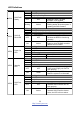
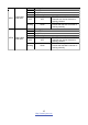
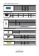
J29/J33: USB Front Panel Connector
Signal Pin Pin Signal
5V Power 1 2 5V Power
D- 3 4 D-
D+ 5 6 D+
GND 7 8 GND
KEY 9 10 NC
J31: PSMI Connector
Pin 1 2 3 4 5
Signal PSMI_Clock PSMI_Data PSU_Alert_L GND
3.3V
Standby
LED1: ID LED
Pin Signal
+ P3V3_AUX
- ID_SW_L
State Color Description
On Blue System identified
Off Off System not identified
NOTE: IPMI can activate ID LED from remote site.
Please visit the TYAN Web Site at http://www.tyan.com
to download the
latest AST2050 Software Configuration Guide for IPMI settings.
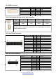
J32: LAN3 Active LED Header
Pin Signal
1
LAN3_ACTIVE_ LED+
1
2
LAN3_ACTIVE_ LED- (GND)
J53: HDD Fault Header
Signal Pin Pin Signal
3.3V Standby 1 2 BMC FRU Clock
GND 3 4 BMC FRU Data
1
5
2
6
KEY 5 6 HDD Fail Input
J59: IPMB Connector
Signal Pin Pin Signal
SMB_BMC_SDA2 1 2 GND
SMB_BMC_SCL2 3 4 NC