Tiger K8WE /// S2877 Version 1.00 Copyright Copyright © TYAN Computer Corporation, 2005-2006. All rights reserved. No part of this manual may be reproduced or translated without prior written consent from TYAN Computer Corp. Trademark All registered and unregistered trademarks and company names contained in this manual are property of their respective owners including, but not limited to the following. TYAN, Taro and Tiger K8WE are trademarks of TYAN Computer Corporation.
Table of Contents Chapter 1: Introduction 1.1 Congratulations 1.2 Hardware Specifications 1.3 Software Specifications Chapter 2: Board Installation 2.1 Board Image 2.2 Block Diagram 2.3 Board Parts, Jumpers and Connectors 2.3.1 Front Panel Header: J139 2.3.2 Clear CMOS Header: J112 2.3.3 Chassis Intrusion Header: J77 2.3.4 *FireWire (IEEE1394A) Enable/Disable Jumper: *J147 2.3.5 *FireWire (IEEE1394A) Pin Header: *J148/*J149 2.3.6 Buzzer/External Speaker Header: J14 2.3.7 COM2 Connector: J42 2.3.8 USB 2.
.4 Getting Help 3.5 BIOS Main Menu 3.6 BIOS Advanced Menu 3.6.1 Hammer Configuration Sub-Menu 3.6.2 Integrated Devices Sub-Menu 3.6.3 PCI Configuration Sub-Menu 3.6.4 IDE Configuration Sub-Menu 3.6.5 Floppy Configuration Sub-Menu 3.6.6 I/O Device Configuration Sub-Menu 3.6.7 Hardware Monitor Sub-Menu 3.6.8 Console Redirection Sub-Menu 3.6.9 Watchdog Timer Option Sub-Menu 3.7 BIOS Memory Menu 3.8 Security Menu 3.9 BIOS Boot Menu 3.9.1 Boot Device Priority 3.10 Power Menu 3.
Chapter 1: Introduction 1.1 - Congratulations You have purchased one of the most powerful entry-level workstation solutions - the Tyan Tiger K8WE (S2877) - based on NVIDIA nForce(tm) Professional Media and Communications Processor (MCP). Designed to support up to two AMD Opteron(tm) 200 series processors, and up to 24GB of Registered DDR400 memory, the S2877 is ideal for video and graphics development applications that demand the highest level of performance from the CPU, memory, and video subsystems. 1.
DDR •Supports ECC with CHIPKill technology •Supports DDR400, DDR333, or DDR266 Expansion Slots •Two x16 PCI Express expansion slots •- Slot 3 PCI-E x16 from nForce PRO 2200 with x4 signals •- Slot 5 PCI-E x16 from nForce PRO 2200 with x16 signals •Four 32-bit 33Mhz PCI v2.3 (Slot 0, Slot 1, Slot 2 and Slot 4) •Total of six usable slots Integrated I/O Ports •One floppy connector supports up to two drives •Four USB 2.
•Watchdog Timer support •Temperature, voltage and fan monitoring 1.3 - Software Specifications OS (Operating System) Support Windows 2000 Server Windows 2000 Advanced Server Windows XP 32bit Windows XP 64bit+sp1 Windows 2003 Server Windows 2003 Server 64bit SuSE Enterprise Server 8.0 AMD64 SuSE 9.2 pro 32bit SuSE 9.3 pro 32bit TYAN reserves the right to add support or discontinue support for any OS with or without notice. Remember to visit TYAN’s website at http://www.tyan.com.
NOTES: 7 http://www.tyan.
Chapter 2: Board Installation Precautions: The Tiger K8WE supports SSI, EPS12V type power supplies (24pin + 8pin) and will not operate with any other types. For proper power supply installation procedures see page 36. DO NOT USE ATX 2.x or ATXGES power supplies as they will damage the board and void your warranty. How to install our products right… the first time The first thing you should do is reading this user’s manual. It contains important information that will make configuration and setup much easier.
2.1- Board Image This picture is representative of the latest board revision available at the time of publishing. The board you receive may or may not look exactly like the above picture. The following page includes details on the vital components of this motherboard. 9 http://www.tyan.
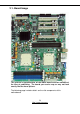
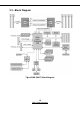
2.2 - Block Diagram Tiger K8WE (S2877) Block Diagram 10 http://www.tyan.
2.3 - Board Parts, Jumpers and Connectors This diagram is representative of the latest board revision available at the time of publishing. The board you receive may not look exactly like the above diagram. NOTE: * is only available on S2877ANRF version. ** is only available on S2877G2NR version. 11 http://www.tyan.
Jumper Legend OPEN - Jumper OFF, without jumper cover CLOSED – Jumper ON, with jumper cover Jumper/Connector Function Settings J139 Front Panel Header See Section 2.3.1 J112 Clear CMOS Jumper See Section 2.3.2 J77 Chassis Intrusion Header See Section 2.3.3 *J147 FireWire (IEEE1394A) Disable Jumper FireWire (IEEE 1394A) Pin Header Buzzer/ External Speaker Header See Section 2.3.4 J42 COM2 Connector See Section 2.3.7 J25/J140 USB2.0 Front Panel Header See Section 2.3.
2.3.1 Front Panel Header: J139 Function PIN # PIN # Function HDD LED+ 1 2 PWR LED+ HDD LED- 3 4 PWR LED- Reset Button - 5 6 PWR Button+ Reset Button + 7 8 PWR Button- VCC 9 10 NC IRRX 11 12 VCC GND 13 14 KEY IRTX 15 16 GND NC 17 18 SPKR 2.3.2 Clear CMOS Header: J112 Pin_3 Pin_1 Pin_3 Pin_1 Clear Default You can reset the CMOS settings by using this jumper if you have forgotten your system/setup password or need to clear system BIOS setting.
2.3.3 Chassis Intrusion Header: J77 Pin-2 GND PIN2 Pin-1 INTRUDUER _L PIN1 The Chassis Intrusion Header provides chassis intrusionmonitoring function. Note: For use with chassis that support this feature 2.3.4 *FireWire (IEEE1394A) Enable/Disable Jumper: *J147 1 Use this jumper to enable/disable IEEE1394. Open : Enable (Default) Closed : Disable Note: J147 is only available on S2877ANRF version. 14 http://www.tyan.
2.3.5 *FireWire (IEEE1394A) Pin Header: *J148/*J149 Signal Pin Pin Signal NC1 1 2 Key TPA + 3 4 TPA ? GND 5 6 GND TPB + 7 8 TPB ? +12V 9 10 +12V GND 11 12 GND NC2 13 14 Key Note: J148 & J149 are only available on S2877ANRF version. 2.3.
2.3.7 COM2 Connector: J42 Signal Description Pin # Pin # Signal Description Data-Carrier Detect 1 2 Data-SetReady Receive-Data 3 4 Request-toSend Transfer-Data 5 6 Clear-to-Send DataTerminalReady 7 8 Ring-Indicator Ground 9 10 Key Use these pin definitions to connect a port to COM2. 2.3.8 USB 2.
2.3.9 Keyboard Lock Connector: J13 Open Closed Use this Jumper to enable/disable PS/2 keyboard. Open : Enable (Default) Closed : Disable 2.3.10 Gigabit LAN1/**LAN2 Front Panel Header: J2/ **J3 PIN1 Pin # Signal Description 1 1000Mb+/100Mb-_Link 2 1000Mb-/100Mb+_Link 3 Active- 4 Active+ Use this 4-Pin Header to connect LAN LED on Front Panel. Note: J3 is only available on S2877G2NR version. 17 http://www.tyan.
2.3.11 **VGA (ATI Rage XL) Enable/ Disable Jumper: **J85 Open Closed Use this Jumper to enable/disable onboard ATI Rage XL graphic. Open : Enable (Default) Closed : Disable Note: J85 is only available on S2877G2NR version. 2.3.12 **BCM5705 Gigabit LAN Enable/ Disable Jumper: **J152 Open Closed Use this Jumper to enable/disable LAN2 (BCM5705 GbE LAN) Open : Enable (Default) Closed : Disable Note: J152 is only available on S2877G2NR version. 18 http://www.tyan.
2.3.13 *Front Panel Audio Header: *P53 Signal Description Pin # Pin # Signal Description AUD_MIC_L 1 2 GND AUD_MIC_R 3 4 AVDD AUD_FP_R 5 6 AUD_RET_R F_AUD_DET 7 8 KEY AUD_FP_L 9 10 AUD_RED_L Note: a. If you use onboard Audio port, you must close Pin5-Pin6 and Pin9-Pin10. b. P53 is only available on S2877ANRF version. 2.3.14 CPU FAN Connector: J9/J37 PIN1 Use these connectors to connect processor cooling fans to your motherboard. J9 for CPU1 & J37 for CPU2.
2.3.15 Chassis 4-pin FAN Connector: J47 PIN1 Use this connector to connect chassis cooling fan to your motherboard. This 4-pin fan connector supports a new standard fan with integrated fan speed control on the fan itself for better fan life. 2.3.16 Chassis 3-pin FAN Connectors: J36/J10 PIN1 Use these connectors to connect chassis cooling fans to your motherboard. The traditional 3-pin fan connector does not have PWM fan speed control function. 20 http://www.tyan.
2.3.17 3-pin or 4-pin fan support selection jumper: J5 Signal Description Pin # Pin # Signal Description GND 6 5 SYS_FAN_PWM GND 4 3 CPU2_FAN_PWM GND 2 1 CPU1_FAN_PWM Pin # Corresponding FAN FAN Connector 1&2 CPU1 FAN J9 3&4 CPU2 FAN J37 5&6 Chassis FAN J47 Open: To support 3-pin auto fan Closed (Default): To support 4-pin auto fan 21 http://www.tyan.
2.4 - Installing the Processor(s) Your brand new Tiger K8WE supports the latest 64-bit processor technology from AMD. Only AMD Opteron™ processor 200 series are certified and supported with this motherboard. Check our website for latest processor support. http://www.tyan.com NOTE If using a single processor, it MUST be installed in socket CPU1. When using a single processor only CPU1 memory banks are addressable. TYAN is not liable for damage as a result of operating an unsupported configuration.
2.5 - Heatsink Retention Frame Installation After you are done installing the processor(s), you should proceed to installing the retention frame and heatsink. The CPU heatsink will ensure that the processors do not overheat and continue to operate at maximum performance for as long as you own them. Overheated processors are also dangerous to the motherboard.
2.6 - Thermal Interface Material There are two types of thermal interface materials designed for use with the AMD Opteron processor. The most common material comes as a small pad attached to the heatsink at the time of purchase. There should be a protective cover over the material. Take care not to touch this material. Simply remove the protective cover and place the heatsink on the processor. The second type of interface material is usually packaged separately.
2.7 - Heatsink Installation Procedures Type A: CAM LEVER (TYPE) INSTALLATION 1. After placing backplate and interface material under motherboard place heatsink retention frame on top of motherboard. Align plastic retention bracket screw holes with CPU backplate standoffs. Tighten screws to secure plastic retention bracket. Repeat for the other side. DO NOT OVER TIGHTEN. 2. After tightening screws secure metal clip to plastic retention bracket center tab. Repeat for the other side of heatsink. 3.
Type B: SCREW RETENTION TYPE HEATSINK 1. After placing CPU back-plate and adhesive interface material under motherboard, place heatsink retention frame on top of motherboard. Align heatsink retention frame screw hole with backplate assembly standoffs. Place heatsink inside plastic retention bracket. Place metal clip over retention frame tab. Repeat for other side. 2. Insert screw through metal clip. BE SURE METAL CLIP IS LOCKED ONTO RETENTION FRAME TAB. 3. Tighten screw through metal clip.
2.8 - Finishing Installing the Heatsink After you have finished installing the heatsink onto the processor and socket, attach the end wire of the fan (which should already be attached to the heatsink) to the motherboard. The following diagram illustrates how to connect fans onto the motherboard. Once you have finished installing all the fans you can connect your drives (hard drives, CD-ROM drives, etc.) to your motherboard. 27 http://www.tyan.
2.9 - Tips on Installing Motherboard in Chassis Before installing your motherboard, make sure your chassis has the necessary motherboard support studs installed. These studs are usually metal and are gold in color. Usually, the chassis manufacturer will pre-install the support studs. If you are unsure of stud placement, simply lay the motherboard inside the chassis and align the screw holes of the motherboard to the studs inside the case.
2.10 - Installing the Memory Before attempting to install any memory, make sure that the memory you have is compatible with the motherboard as well as the processor. The following diagram shows common types of DDR SDRAM modules: Here are a few key points to note before installing memory into your Tiger K8WE: •Always install memory beginning with CPU1 DIMMA1. •In order to access memory on CPU2, both processors must be installed. •Single, pairs are supported on CPU1, four modules is also supported on CPU2.
This following chart outlines the rules for populating memory (Note: X indicates a populated DIMM Slot) Memory Configuration Chart CPU1 CPU1 CPU1 CPU1 DIMM-A1 DIMM-A2 DIMM-B1 DIMM-B2 128 bit memory support X X X X X X X X X CPU2 CPU2 DIMM-A1 DIMM-A2 X X X X X X X X X X X X X X X X 64 bit memory support X X X X X X X X X X X 30 http://www.tyan.
Memory Installation Procedure When you install the memory modules, make sure the module aligns properly with the memory slot. The modules are keyed to ensure that it is inserted only one way. The method of installing memory modules are detailed by the following diagrams. Once the memory modules are firmly seated in the slot, two latches on either side will close and secure the module into the slot. Sometimes you may need to close the latches yourself.
2.11 - Attaching Drive Cables Attaching IDE Drive Cable Attaching the IDE drive cable is simple. The cable is “keyed” to only allow it to be connected in the correct manner. Attaching IDE cable to the IDE connector is illustrated below: Simply plug in the BLUE END of the IDE cable into the motherboard IDE connector, and the other end into the drive. Each standard IDE cable has three connectors, two of which are closer together.
The following pictures illustrate how to connect an SATA drive 1.SATA drive cable connection 2. SATA drive power connection 3. SATA cable motherboard connector 4. SATA drive power adapter Attaching Floppy Drive Cables Attaching floppy diskette drives are done in a similar manner to hard drives. See the picture below for an example of a floppy cable. Most of the current floppy drives on the market require that the cable be installed with the colored stripe positioned next to the power connector.
2.12 - Installing Add-In Cards Before installing add-in cards, it’s helpful to know if they are fully compatible with your motherboard. For this reason, we’ve provided the diagrams below, showing the most common slots that may appear on your motherboard. Not all of the slots shown will necessarily appear on your motherboard. Simply find the appropriate slot for your add-in card and insert the card firmly. Do not force any add-in cards into any slots if they do not seat in place.
2.13 - Connecting External Devices Your motherboard supports a number of different interfaces for connecting peripherals. Some I/O ports may not be available with the board due to the different configurations. PS/2 Mouse/ Keyboard Serial Port **VGA Port Gigabit Ethernet **Gigabit Ethernet *Audio USBx2 This picture is representative of the latest board revision available at the time of publishing. The board you receive may or may not look exactly like the above picture.
2.14 - Tips on modifying I/O shielding for ANRF and G2NR version We have enclosed below I/O shielding, which is compatible with board of both S2877ANRF and S2877G2NR version. The VGA port, GbE LAN2(BCM5705) port and Audio ports are covered with soft metal which can be disassembled easily by hand. a. If you choose the board of S2877ANRF version, please disassemble corresponding soft metal of Audio ports, and keep VGA & LAN2 port shielded. b.
4 8 1 5 EPS 12V 8-pin (CPU Power) 4 GND 8 +12V3 3 GND 7 +12V3 2 GND 6 +12V3 1 GND 5 +12V3 Applying power to the board 1. Connect the EPS 12V 8-pin power connector. 2. Connect the EPS 12V 24-pin power connector. 3. Connect power cable to power supply and power outlet NOTE YOU MUST unplug the power supply from the wall outlet before plugging the power cables to motherboard connectors. 2.
http://www.tyan.
Chapter 3: BIOS Setup 3.1 - BIOS Setup Utility With the BIOS setup utility, you can modify BIOS settings and control the special features of your computer. The setup utility uses a number of menus for making changes and turning the special features on or off. NOTE All menus are based on a typical system. The actual menus displayed on your screen may be different and depend on the hardware and features installed in your computer. To start the BIOS setup utility: a. Turn on or reboot your system b.
3.2 - BIOS Menu Bar The menu bar at the top of the windows lists these selections: Main Advanced Memory Boot Exit NOTE To configure basic system setups To configure the advanced chipset features To configure system memory features To configure system boot order To exit setup utility Options written in bold type represent the BIOS setup default 3.
3.5 - BIOS Main Menu The Main BIOS Menu is the first screen that you can navigate. The Main BIOS setup menu screen has two main frames. The left frame displays all the options that can be configured. "Grayed-out" options cannot be configured, options in blue can be changed. The right frame displays the key legend. Above the key legend is an area reserved for a text message. When an option is selected in the left frame, it is highlighted in white. Often, a text message will accompany it.
3.6 - BIOS Advanced Menu You can select any of the items in the left frame of the screen, such as Hammer Configuration, to go to the sub menu for that item. You can display an Advanced BIOS Setup option by highlighting it using the keys. All Advanced BIOS Setup options are described in this section. The Advanced BIOS Setup screen is shown below. The sub menus are described on the following pages.
Integrated Devices Menu Item Set integrated devices. PCI Configuration Menu Item Configure PCI devices. IDE Configuration Menu Item Configure IDE interface. Floppy Configuration Menu Item Configure floppy interface. I/O Device Configuration Menu Item Peripheral configuration Hardware Monitor Menu Item Console Redirection Menu Item Watchdog Timer Option Menu Item Enable/disable the onboard Hardware monitor device Additional setup menus to configure console.
Feature Option Auto Mem Clock Mode Limit Disabled Node Memory Interleave Enabled Disabled Dram Block Interleave Enabled Disabled Large Memory Simulation MTRR Mapping ACPI SRAT Table Enabled Discrete Continuous Disabled Enabled Description Select Memory Clock frequency. Interleave memory blocks across Processor Nodes. BIOS will auto detect capability of memory system. Interleave memory blocks across dram chip selects. BIOS will auto detect capability on each node.
F1: Help ↑↓: Select Item -/+: Change Values F9: Setup Defaults Esc: Exit ← →: Select Screen Enter: Select Sub-Menu F10: Previous Values Feature USB Control USB BIOS Legacy Support SATA0 Controller SATA1 Controller Interrupt Mode NV RAID Configuration Option Disabled USBA+USBB USBA+ USBB+USB2 Disabled Enabled Enabled Disabled Enabled Disabled PIC Description Set USB controllers. Set support for USB Keyboard/Mouse. Set First Serial ATA device. 8529/PIC Set Second Serial ATA device.
IDE Primary Master IDE Primary Slave IDE Secondary Master IDE Secondary Slave Internal SATA Primary Internal SATA Secondary External SATA Primary External SATA Secondary [Disabled] [Disabled] [Disabled] [Disabled] [Disabled] [Disabled] [Disabled] [Disabled] F1: Help ↑↓: Select Item -/+: Change Values F9: Setup Defaults Esc: Exit ← →: Select Screen Enter: Select Sub-Menu F10: Previous Values Feature NV Configuration IDE Primary/Secondary Master/Slave Internal SATA Primary/Secondary External SATA Primary
PCI PCI PCI PCI Device, Slot # 1 Device, Slot # 2 Device, Slot # 3 Device, Slot # 4 Onboard Device Control Option ROM Placement [Disabled] PCI/PNP ISA UHB Region Exclusion PCI/PNP ISA IRQ Resource Exclusion F1: Help ↑↓: Select Item -/+: Change Values F9: Setup Defaults Esc: Exit ← →: Select Screen Enter: Select Sub-Menu F10: Previous Values Feature PCI Device, Slot #1 ,2,3& 4 Option Menu Item PCI/PNP ISA UHB Region Exclusion Menu Item PCI/PNP ISA IRQ Resource Exclusion Menu Item Descripti
Option ROM Scan: Enable Master: Latency Timer [Enabled] [Disabled] [Default] Item Specific Help F1: Help ↑↓: Select Item -/+: Change Values F9: Setup Defaults Esc: Exit ← →: Select Screen Enter: Select Sub-Menu F10: Previous Values Feature Option Enabled Disabled Disabled Option ROM Scan Enable Master Enabled Default Latency Timer 0020h Description Initialize device expansion ROM. Enable selected device as a PCI bus master.
F1: Help ↑↓: Select Item -/+: Change Values F9: Setup Defaults Esc: Exit ← →: Select Screen Enter: Select Sub-Menu F10: Previous Values PCI/PNP ISA UHB Region Exclusion You can use this screen to select options for the PCI/PNP ISA UHB Region Exclusion settings. Use the up and down keys to select an item. Use the and keys to change the value of the selected option.
PCI/PNP ISA IRQ Resource Exclusion You can use this screen to select options for the PCI/PNP IRQ Resource Exclusion settings. Use the up and down keys to select an item. Use the and keys to change the value of the selected option.
3.6.4 - IDE Configuration Sub-Menu You can use this screen to select options for the IDE Configuration settings. Use the up and down keys to select an item. Use the and keys to change the value of the selected option.
Primary Master/Slave, Secondary Master/Slave The following screen shows the information of IDE device.
Disabled Ultra DMA Mode Enabled Select the Ultra DMA mode used for moving data to/from the drive. 3.6.5 - Floppy Configuration Sub-Menu You can use this screen to select options for the Floppy Configuration settings. Use the up and down keys to select an item. Use the and keys to change the value of the selected option.
3.6.6 - I/O Device Configuration Sub-Menu You can use this screen to select options for the I/O Device Configuration settings. Use the up and down keys to select an item. Use the and keys to change the value of the selected option.
Interrupt Parallel port Base I/O Address Interrupt Mode DMA channel Floppy disk controller Base I/O address IRQ3 IRQ4 Disabled Enabled 378 278 IRQ5 IRQ7 Output only Bi-directional DMA 1 DMA 3 Disabled Enabled Primary Secondary Set the interrupt for serial port B Configure parallel port using options. Set the base I/O address for parallel port. Set the interrupt for parallel port. Set the mode for parallel port using options. Set the DMA channel for parallel port.
3.6.8 – Console Redirection Sub-Menu You can use this screen to select options for the Console Redirection settings. Use the up and down keys to select an item. Use the and keys to change the value of the selected option. PhoenixBIOS Setup Utility Advanced Com Port Address [Disabled] Baud Rate Console Type Flow Control Console connection Continue C.R.
Direct Console connection Via modem Continue C.R. after POST Off On Indicate whether the console is connected directly to the system or a modem is used to connect. Enable Console Redirection after OS has loaded. 3.6.9– Watchdog Timer Option Sub-Menu You can use this screen to select options for the Watchdog settings. Use the up and down keys to select an item. Use the and keys to change the value of the selected option.
3.7 - BIOS Memory Menu This menu has options for memory speed & latency. Use the up and down keys to select an item. Use the and keys to change the value of the selected option.
Feature Option Disabled Enabled Disabled Memory Cache Cache A000-AFFF Cache B000-BFFF USHC Write Through Description Set the state of memory cache. Control caching of the memory blocks. Write Protect Write Back Cache C800-CBFF ~ Cache EC00-EFFF Disabled Write Through Write Protect Write Back Control caching of the memory blocks. 3.8 - Security Menu This menu has options for the Security options. Use the up and down keys to select an item.
Feature Option Disabled Enabled Normal Password on boot Fixed disk boot sector Write Protect User Supervisor Diskette access Disabled Virus check reminder Daily Disabled System back reminder Daily Description Enable password entry on boot. Write protects boot sector on hard disk to protect against viruses. Control access to diskette drives. Display reminder message at boot (daily, every Monday or 1st of every month). Display reminder message at boot (daily, every Monday or 1st of every month). 3.
Feature Option Disabled Enabled Disabled Enabled Disabled Enabled QuickBoot Mode Boot-time Diagnostic Screen Summary screen Boot Device Priority Menu Item Description Allow the system to skip certain tests while booting. Display the diagnostic screen during boot. Display system configuration on boot. Select the search order for the types of boot devices. 3.9.1 - Boot Device Priority You can use this screen to select options for the Boot Device Priority settings.
3.10 - Power Menu This menu has options for the Power management. Use the up and down keys to select an item. Use the and keys to change the value of the selected option.
Power Loss Control Enable Stay Off Power On Spectrum. Control power loss. 63 http://www.tyan.
3.11 - BIOS Exit Menu This menu has options for the Exit Priority. Use the up and down keys to select an item. Use the and keys to change the value of the selected option. PhoenixBIOS Setup Utility Exit Exit Saving Charges Exit Discarding Changes Item Specific Help Exit System Setup and save your changes to CMOS.
http://www.tyan.
Chapter 4: Diagnostics Note: if you experience problems with setting up your system, always check the following things in the following order: Memory, Video, CPU By checking these items, you will most likely find out what the problem might have been when setting up your system. For more information on troubleshooting, check the TYAN website at: http://www.tyan.com. 4.1 Beep Codes Fatal errors, which halt the boot process, are communicated through a series of audible beeps.
4.
2Eh 2Fh 30h Code 6Ah 6Bh 6Ch 6Eh 70h 72h 76h 7Ch 7Eh 80h 81h 82h 83h 84h 85h 86h. 87h 88h 89h 8Ah 8Bh 8Ch 8Fh 90h 91h 1-3-4-3. RAM failure on data bits of low byte of memory bus Enable cache before system BIOS shadow 1-4-1-1.
92h Jump to UserPatch2 C7h 93h Build MPTABLE for multiprocessor boards Install CD ROM for boot C8h 95h 96h C9h D2h Extended checksum (optional) BIOS Boot Block E0h E1h BIOS Boot Block BIOS Boot Block E2h Initialize the CPU E3h E4h E5h Initialize system timer Initialize system I/O Check force recovery boot E6h E7h Checksum BIOS ROM Go to BIOS E8h Code F1h F2h F3h Set Huge Segment Beeps / Description Initialize Run Time Clock Initialize video Initialize System Management Mode Output one beep
Glossary ACPI (Advanced Configuration and Power Interface): a power management specification that allows the operating system to control the amount of power distributed to the computer’s devices. Devices not in use can be turned off, reducing unnecessary power expenditure. AGP (Accelerated Graphics Port): a PCI-based interface which was designed specifically for demands of 3D graphics applications. The 32-bit AGP channel directly links the graphics controller to the main memory.
losing your data should the system crash. Information in a buffer is temporarily stored, not permanently saved. Bus: a data pathway. The term is used especially to refer to the connection between the processor and system memory, and between the processor and PCI or ISA local buses. Bus mastering: allows peripheral devices and IDEs to access the system memory without going through the CPU (similar to DMA channels). Cache: a temporary storage area for data that will be needed often by an application.
DRAM (Dynamic RAM): widely available, very affordable form of RAM which looses data if it is not recharged regularly (every few milliseconds). This refresh requirement makes DRAM three to ten times slower than non-recharged RAM such as SRAM. ECC (Error Correction Code or Error Checking and Correcting): allows data to be checked for errors during run-time. Errors can subsequently be corrected at the same time that they’re found.
I/O (Input/Output): the connection between your computer and another piece of hardware (mouse, keyboard, etc.) IRQ (Interrupt Request): an electronic request that runs from a hardware device to the CPU. The interrupt controller assigns priorities to incoming requests and delivers them to the CPU. It is important that there is only one device hooked up to each IRQ line; doubling up devices on IRQ lines can lock up your system. Plug-n-Play operating systems can take care of these details for you.
PXE (Preboot Execution Environment): one of four components that together make up the Wired for Management 2.0 baseline specification. PXE was designed to define a standard set of preboot protocol services within a client with the goal of allowing networked-based booting to boot using industry standard protocols. RAID (Redundant Array of Independent Disks): a way for the same data to be stored in different places on many hard drives.
SDRAM (Static RAM): unlike DRAM, this type of RAM does not need to be refreshed in order to prevent data loss. Thus, it is faster and more expensive. Standby mode: in this mode, the video and hard drives shut down; all other devices continue to operate normally. UltraDMA-33/66/100: a fast version of the old DMA channel. UltraDMA is also called UltraATA. Without a proper UltraDMA controller, your system cannot take advantage of higher data transfer rates of the new UltraDMA/UltraATA hard drives.
Technical Support If a problem arises with your system, you should turn to your dealer for help first. Your system has most likely been configured by them, and they should have the best idea of what hardware and software your system contains. Furthermore, if you purchased your system from a dealer near you, you can bring your system to them to have it serviced instead of attempting to do so yourself (which can have expensive consequences). Help Resources: 1. See the beep codes section of this manual. 2.
Notice for the USA Compliance Information Statement (Declaration of Conformity Procedure) DoC FCC Part 15: This device complies with part 15 of the FCC Rules Operation is subject to the following conditions: This device may not cause harmful interference, and This device must accept any interference received including interference that may cause undesired operation.