AST2050 User Guide V1.
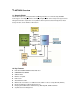
1. AST2050 Overview 1.1. About AST2050 The AST2050 chipset is an Integrated Remote Management Processor introduced by ASPEED Technology Inc. It is a high performance and highly integrated SOC device designed to support various management functions required for server platforms which require baseboard management, virtual storage functions, and/or KVM-over-IP functions. 1.2. Key Features Embedded 200MHz ARM926 32-bit RISC CPU 64MB DDR2-400 SDRAM 8MB SPI Flash IPMI 2.
1.3. IPMI and KVM-over-IP Products TYAN currently creates 2 different SKUs of the AST2050 product. One is an IPMI only version which provides full IPMI management. The other is a KVM-over-IP version which includes all the functionality of the IPMI only version, but also with the added features of KVM-over-IP and virtual storage support.
2. Using the AST2050 The AST2050 allows both local and remote access to the BMC. For local access to the AST2050 chipset users may utilize the local LPC bus through a utility called KCSFLASH. Users may also choose a IPMI utility of their choice including open source tools such as IPMITool, OpenIPMI, IPMI Util or TYAN’s UH8 IPMI utility. The UH8.exe utility is available through the TYAN website.
3. Aster GUI In the next following sections we will detail each part of the Aster GUI. You will find detailed information about the System Information, Server Health, Configuration, Remote Control, Maintenance and Language settings. 3.1. How to Login into the Aster GUI Any Java and HTTPS Enabled Web browser may be used to access the AST2050 Web GUI. Enter the IP address of the AST2050 in the address bar and you will be redirected to the login page. You will be prompted to enter a user name and password.
3.2. System Information Tab The System Information tab will show the system power on status, firmware revision, release date and build time. 3.3. Server Heath Tab The Server Health tab contains options to show the motherboard sensor readings and events. The Sensor Data Repository (SDR), Sensor Reading, Sensor Event Log (SEL) and Platform Event Filters (PEF) are all implemented in compliance with the IPMI2.0 specification.
3.3.1 Sensor Reading This page displays sensor information including readings and status. You can toggle viewing the thresholds for the sensors by pressing the Show Thresholds button.
3.3.2 Event Log This section show you data related to the servers health, such as sensor readings and the event log.
3.4 Configuration Tab This page contains options to configure Alerts, Mouse mode, Network, SMTP, Users, and Date/Time NTP Settings. 3.4.1 Alerts This page allows the user to configure how the BMC handles IPMI alerts. Alert destinations may be set to allow the system to send notifications when pre-programmed conditions are met. Test alerts may also be sent from this menu to test the notification settings.
Note: When configuring the Alerts setting, please confirm that you have ENABLED Platform Event Filter (PEF) first in the bios. On some motherboards, the BIOS will disable PEF as the default setting. You can check it in the BIOS setup or by using UH8 to check if PEF is enabled properly. 3.4.1.1 Modify Alert The Modify Alert page contains drop down menus and fields to configure alert types (email, SNMP traps), event severity, destination IP/Email address, and subject etc.
3.4.2 Mouse Mode This configuration is contingent on the OS that is installed on the Local Host and the destination machine you will manage. Most current Microsoft OS’s (2000, XP, 2003, Vista, 2008) and Mac OS X use Absolute Mode. Relative mode is used by most Linux distributions (SuSE, RHEL) and older operating systems like Windows 95/98. 3.4.3 Network You can view and modify the network settings from this section.
3.4.4 SMTP Use this page to configure the IP address for the SMTP Mail server. 3.4.5 Users Use this page to add, modify, and delete users. You may select “modify user” and then change each user’s name, password and their associated privileges.
3.4.6 Date Time/NTP Settings Select options to set date/time and Synchronize with the NTP server.
3.5 Remote Control This tab allows the user to perform various remote operations such as “Console Redirection”, “Power Control” and “Other Control”. There are various different SKU’s for your particular motherboard that include various options for IPMI functions. If you try to use options that are not directly supported by your particular motherboard version, you will receive various alert messages to let you know that particular feature is not supported on your version.
3.5.1 Remote Console Redirection Press the “Java Console” button to invoke the JVIEWER to start a KVM-over-IP session 3.5.1.
2) Keyboard - To avoid any problems with special key combination interference, you may need to use this drop down menu to send special Key combinations to the remote OS. 3) Mouse - Select to allow the mouse to work correctly within the JViewer remote screen (in sync with remote OS). Press to release “mouse sync” and return mouse control to local OS.
4) Options – Select menu to configure KVM-over-IP Video engine or the bandwidth settings 5) Device – You can choose from a redirect list of CD-ROM, ISO, Floppy or Floppy Image
Choose a local CD-ROM drive to redirect to the remote system. Note: You will need to configure the “Boot order” on the remote system (via remote station BIOS Setup, after selecting the CD-ROM to redirect) before the remote system will boot from the redirected CD-ROM.
3.5.2 Power Controls and Status Various options are available on this page to reset power, power off, power on or power cycle the remote system. 3.5.3 Other Controls Select options on this page to locate a particular chassis through a LED ID check, clear CMOS and lock control to the local system through the remote system.
3.6 Maintenance This section allows you to perform maintenance tasks on a remote device. 3.6.1 Firmware Update Select firmware to upload and then press “update firmware” button to precede with a firmware update.
3.6.2 Pre-reserve Configuration The BMC will verify the firmware version. If a new a firmware has been found, then a warning message will appear to state that an uploaded image is different than the current version. If you wish to update your firmware, one important step to consider is the Preserve Configuration check box. Preserve Configuration means that the flash tool will keep the previous configuration (ie. SDR, FRU, LAN configuration and etc).
3.7 Group Control The page allows you to control multiple BMC’s at the same time. The machine that you are currently logged into through the AST2050 chipset will be named “localhost”. You can then use this screen to get Model, Power Status, Sensor, SEL and Front Panel Lockout information for all the other systems that are connected. 3.7.
3.7.2 localhost Event Log Click “SEL” and you will get the system event logs of the Host that you chose. 3.7.3 Add Host Click “Add Host” button to add additional host systems.
Input BMC IP address, user name and password. The Username and password of new BMC are shared with localhost by default. Of course, you could type the correct one if different.
3.7.4 Delete Host You can use the “Del Host(s)” button to delete any host on the list. Click the line of host(s) you want to select, click the “Select” button and you will find the “Selected” value become “Yes”. Only once a host(s) has been selected can it be deleted.
If the BMC is malfunctioning or not responding properly, the response column will display a wait.
4 Section 3.0 SMASH Command Line Protocol in AST2050/Pilot-2 4.0 Quick View SMASH Command Line Protocol(SMASH CLP) provides server administrators a consistent command line interface for server monitoring and management tasks. It is a simple and standard way to access the Pilot-2 BMC. 4.1Enter/Exit of the SMASH CLP Console Start SMASH Command Line Protocol (CLP) console via SSH. Start the SSH client, the user name and password are same as what was used with the web interface of the Pilot-II.
Enter the SMASH-CLP Console
Type ->exit to exit SMASH CLP Console
4.2 Features 4.2.
A user can get the system power status under “system1” by using the following command: “->cd /system1” “->show” A user can use basic terms such as “start”, “stop” and “reset” on through the console by using the following command: “->cd /system1” “->start” or “->stop” or “->reset”
4.2.2 Serial Terminal Under the SMASH-CLP, a user could redirect host serial port 1 to the remote console. A user will need to make sure that the SOL baud rate configuration matches the host serial port setting.
To exit serial terminal, user need type following keys: “Enter”+”Esc”+”t”. 4.2.3.
4.2.
4.2.
4.2.6 BMC users account configuration A user can update the user account under “/system1/sp1” by using the following commands: “->cd /system1/sp1/accountX” (X is account number) “->set username=xxxx” to change user name “->set password=xxxx” to change password “->set enabledstate=1/0” to enable/disable this account.
4.2.
User could change IP address, subnet mask or use dhcp. After changing these values, the user will need to save them by setting property “committed”. “->set ipaddress=192.168.0.
Section 5 IPMI OS Drivers and Open Source Software The AST2050 is designed to operate independently of an operating system and does not require any additional drivers or software for remote access.
access will not allow you to access the IPMI chipset from the local machine. In order to access the IPMI chipset from the local machine a third party IPMI utility such as IPMI tool must be used. The AST2050 firmware is fully compliant with the IPMI 2.0 specification which allows the use of standard IPMI drivers embedded in most current operating systems. 5.1 Windows IPMI Driver The AST2050 chipset supports Intel reference drivers. They are available direct from Microsoft’s website.
There is no software to install to use IPMI with these motherboards. It is all provided through a web interface. Refer to the AST2050 manual for complete instructions on how to use this interface. Simply point your web browser to the IP address of the BMC of the motherboard you want to monitor. 2: How do I find the IP address of the BMC? The BMC will display its IP address during POST. through another computer on the network.