Touchmonitor User Guide 1937L 19” LCD Rear-Mount Touchmonitor
Elo TouchSystems 19” LCD REAR-MOUNT Touchmonitor User Guide Revision B P/N E508220 Elo TouchSystems 1-800-ELOTOUCH www.elotouch.
Copyright © 2009 Tyco Electronics. All Rights Reserved. No part of this publication may be reproduced, transmitted, transcribed, stored in a retrieval system, or translated into any language or computer language, in any form or by any means, including, but not limited to, electronic, magnetic, optical, chemical, manual, or otherwise without prior written permission of Tyco Electronics. Disclaimer The information in this document is subject to change without notice.
Table of Contents Chapter 1 Introduction 1 Product Description 1 Precautions ................................................................. 1 Chapter 2 Installation and Setup 2 Unpacking Your Touchmonitor ...................................... 2 Interface Connection ................................................... 3 Power Requirements ................................................... 3 Product Overview ....................................................... 4 Main Unit .......................
CHAPTER 1 INTRODUCTION Product Description Your new touchmonitor combines the reliable performance of touch technology with the latest advances in (LCD) display design. This combination of features creates a natural flow of information between a user and your touchmonitor. This LCD monitor incorporates a 19” color active matrix thin-film-transistor (TFT) to provide superior display performance. A maximum resolution of SXGA 1280 x 1024 is ideal for displaying graphics and images.
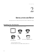
CHAPTER 2 INSTALLATION AND SETUP This chapter discusses how to install your LCD touchmonitor and how to install the driver software. Unpacking Your Touchmonitor Check that the following 7 items are present and in good condition: LCD monitor Video cable USB cable Elo QuickStart CD Software Serial cable (exclude APR model) Brackets Touch Tools CD + Quick Install Guide *Optional external DC (power brick) Power brick and cables: 12V, 4.16A, 50W-R, available at additional cost.
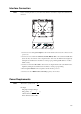
Interface Connection NOTE: Before connecting the cables to your touchmonitor and PC, be sure that the computer and touchmonitor are turned off. 1 Adapter 3 2 Video Cable 2 Serial Cable USB Cable 5 OSD Remote Control Key (option) 1. Connect one end of the power adapter to the monitor and the other end to the connector of the power cord. 2.
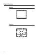
Product Overview Main Unit Rear View 2-4
Installing the Driver Software Elo TouchSystems provides driver software that allows your touchmonitor to work with your computer. Drivers are located on the enclosed CD-ROM for the following operating systems: • Windows 7 • Windows Vista • Windows XP • Windows 2000 • Windows Me • Windows 98 • Windows 95 • Windows NT 4.0 • Windows 3.1 • MS-DOS Additional drivers and driver information for other operating systems are available on the Elo TouchSystems web site at www.elotouch.com.
Installing the Serial Touch Driver (not applicable to Acoustic Pulse Recognition monitor) Installing the Serial Touch Driver for Windows 7, Windows Vista, Windows XP, Windows 2000, ME, 95/98 and NT4.0. NOTE: For Windows 2000 and NT4.0 you must have administrator access rights to install the driver. Make sure the serial connector (RS232) is plugged into the monitor and an open com port on the PC. 1 Insert the Elo CD-ROM in your computer's CD-ROM drive.
Installing the Serial Touch Driver for MS-DOS and Windows 3.1 You must have a DOS mouse driver (MOUSE.COM) installed for your mouse if you wish to continue using your mouse along with your touchmonitor in DOS. To install Windows 3.x and MS-DOS touch driver from Windows 95/98, follow the directions below: 1 Insert the CD-ROM in your computer’s CD-ROM drive. 2 From DOS, type d: and press the Enter key to select the CD-ROM (your CD-ROM drive may be mapped to a different drive letter).
Installing the USB Touch Driver Installing the USB Touch Driver for Windows 7, Windows Vista, Windows XP, Windows 2000, ME and Windows 98. 1 Insert the Elo CD-ROM in your computer’s CD-ROM drive. If Windows 98 or Windows 2000 starts the Add New Hardware Wizard, do the following: 2 Choose Next. Select “Search for the best driver for your device (Recommended)” and choose Next.
CHAPTER 3 OPERATION About Touchmonitor Adjustments Your touchmonitor will not likely require adjustment. However, variations in video output and application may require adjustments to the touchmonitor to optimize the quality of the display. For best performance, your touchmonitor should be operating in native resolution, that is 1280 x 1024 at 80k-75 Hz. Use the Display control panel in Windows to choose 1280 x 1024 resolution. Operating in other resolutions will degrade video performance.
Rear Panel Controls SEL MENU 1 2 Control 1 Menu/Exit 2 3 4 5 Function Display/exits the On Screen Display (OSD) menus. 1. Enter contrast of the OSD. 2. Increase value of the adjustment item. 3. Select item clockwise. 1. Enter brightness adjustment. 2. Decrease value of the adjustment item. 3. Select item counter-clockwise. Selects the adjustment items from the OSD menus. Switches the power of the monitor.
Controls and Adjustment On Screen Display (OSD) Menu Functions To Display and Select the OSD Functions: 1 Press the Menu key to activate the OSD menu. 2 Use or to move clockwise or counter-clockwise through the menu. Press the Select key, the parameter will be highlighted when selected. 3 To quit the OSD screen at any time during the operation, press the Menu key. If no keys are pressed for a short time period, the OSD automatically disappears.
On Screen Display (OSD) Control Options Control Contrast Brightness V-Position H-Position Recall Defaults RGB Exit Sharpness Phase Clock OSD H-Position OSD V-Position OSD Time Auto-Adjust OSD Language Information Description 3-12 Description Increases or decreases contrast. Increases or decreases brightness. Moves the screen up or down. Moves the screen left or right. Returns the monitor to its default settings. Press or to select 9300, 6500, 5500, 7500 and USER.
Preset Modes To reduce the need for adjustment for different modes, the monitor has default setting modes that are most commonly used as given in the table below. If any of these display modes are detected, the monitor automatically adjusts the picture size and centering. When no mode is matched, the user can store their preferred modes in the user modes. The monitor is capable of storing up to 7 user modes.
Power Mode On Sleep Off Power Consumption <50W <4W <2W We recommend switching the monitor off when it is not in use for a long time. NOTE: Complies to VESA Power Management (DPM) standards. To activate the monitor, press any key on the keyboard or move the mouse or touch the touchscreen. In order for the touchscreen to bring the monitor from the DPM system, the touchscreen function must be fully operational.
C HAPTE R 4 TROUBLESHOOTING If you are experiencing trouble with your touchmonitor, refer to the following table. If the problem persists, please contact your local dealer or our service center. Solutions to Common Problems Problem The monitor does not respond when turning on the system. Suggestion(s) 1. Check that the monitor’s Power Switch is on. 2. Turn off the power and check the monitor’s DC power cord and signal cable for proper connection.
APPENDI X A NATIVE RESOLUTION The native resolution of a monitor is the resolution level at which the LCD panel is designed to perform best. For the LCD touchmonitor, the native resolution is 1280 x 1024 for the 19 inch size. In almost all cases, screen images look best when viewed at their native resolution. You can lower the resolution setting of a monitor but not increase it.
As an example, a SXGA resolution LCD panel has 1280 pixels horizontally by 1024 pixels vertically. Input video is also represented by the same terms. SXGA input video has a format of 1280 pixels horizontally by 1024 pixels vertically. When the input pixels contained in the video input format match the native resolution of the panel, there is a one to one correspondence of mapping of input video pixels to LCD pixels.
APPENDI X B TOUCHMONITOR SAFETY This manual contains information that is important for the proper setup and maintenance of your touchmonitor. Before setting up and powering on your new touchmonitor, read through this manual, especially Chapter 2 (Installation), and Chapter 3 (Operation). 1 To reduce the risk of electric shock, follow all safety notices and never open the touchmonitor case. 2 Turn off the product before cleaning.
Care and Handling of Your Touchmonitor The following tips will help keep your touchmonitor functioning at the optimal level. • To avoid risk of electric shock, do not disassemble the brick power supply or display unit cabinet. The unit is not user serviceable. Remember to unplug the display unit from the power outlet before cleaning. • Do not use alcohol (methyl, ethyl or isopropyl) or any strong dissolvent. Do not use thinner or benzene, abrasive cleaners or compressed air.
APPENDI X C TECHNICAL SPECIFICATIONS C-20
Touchmonitor Specifications Model LCD Display Display Size Pixel Pitch Display Mode Native Resolution Contrast Ratio Brightness Response Time (Rise or Fall) Display Color Viewing Angle (CR>10, typical) Input Signal Video Sync Signal Connector Rear Controls On Screen Display (OSD) Controls Plug & Play Touch Panel (optional) Operating Conditions Storage Conditions Dimensions (HxWxD) Weight (Net) Certifications Temperature Humidity Altitude Temperature Humidity 1937L 19” TFT Active Matrix Panel 376.
19” LCD Touchmonitor (1937L) Dimensions C-22
REGULATORY INFORMATION I. Electrical Safety Information: A) Compliance is required with respect to the voltage, frequency, and current requirements indicated on the manufacturer’s label. Connection to a different power source than those specified herein will likely result in improper operation, damage to the equipment or pose a fire hazard if the limitations are not followed. B) There are no operator serviceable parts inside this equipment.
D) General Information to all Users: This equipment generates, uses and can radiate radio frequency energy. If not installed and used according to this manual the equipment may cause interference with radio and television communications. There is, however, no guarantee that interference will not occur in any particular installation due to site-specific factors.
III.
WARRANTY Except as otherwise stated herein or in an order acknowledgment delivered to Buyer, Seller warrants to Buyer that the Product shall be free of defects in materials and workmanship. The warranty for the touchmonitors and components of the product is 3 (three) years. Seller makes no warranty regarding the model life of components. Seller’s suppliers may at any time and from time to time make changes in the components delivered as Products or components.
THESE REMEDIES SHALL BE THE BUYER’S EXCLUSIVE REMEDIES FOR BREACH OF WARRANTY. EXCEPT FOR THE EXPRESS WARRANTYSET FORTHABOVE, SELLERGRANTS NO OTHER WARRANTIES, EXPRESS OR IMPLIED BY STATUTE OR OTHERWISE, REGARDING THE PRODUCTS, THEIR FITNESS FOR ANY PURPOSE, THEIR QUALITY, THEIR MERCHANTABILITY, THEIR NONINFRINGEMENT, OR OTHERWISE. NO EMPLOYEE OF SELLER OR ANY OTHER PARTY IS AUTHORIZED TO MAKE ANY WARRANTY FOR THE GOODS OTHER THAN THE WARRANTY SET FORTH HEREIN.
Check out Elo’s Website! www.elotouch.com Get the latest... • Product information • Specifications • News on upcoming events • Press release • Software drivers • Touchmonitor Newsletter Getting in Touch with Elo To find out more about Elo’s extensive range of touch solutions, visit our Website at www.elotouch.com or simply call the office nearest you: North America Germany Belgium Asian-Pacific Elo TouchSystems Tyco Electronics Raychem GmbH Tyco Electronics Raychem GmbH Sun Homada Bldg.