Operator’s Manual MM-011553-001 Rev.
MM-011553-001, Rev. A MANUAL REVISION HISTORY REV DATE A Jul/07 Apr/08 REASON FOR CHANGE Initial Release. Updated operating information. M/A-COM Technical Publications would particularly appreciate feedback on any errors found in this document and suggestions on how the document could be improved. Submit your comments and suggestions to: Tyco Electronics Wireless Systems Segment M/A-COM, Inc.
MM-011553-001, Rev. A TABLE OF CONTENTS Page 1 SAFETY SYMBOL CONVENTION.................................................................................................... 6 2 RF ENERGY EXPOSURE INFORMATION ..................................................................................... 7 2.1 RF ENERGY EXPOSURE AWARENESS, CONTROL INFORMATION, AND OPERATION INSTRUCTIONS FOR FCC OCCUPATIONAL USE REQUIREMENTS ................................ 7 2.1.1 Federal Communications Commission Regulations......
MM-011553-001, Rev. A TABLE OF CONTENTS Page 6.19 6.20 6.21 6.22 6.23 6.24 6.25 6.26 6.27 6.28 6.29 6.30 6.31 6.32 6.33 6.34 6.18.1 Enabling Stealth Mode .................................................................................................. 25 6.18.2 Disabling Stealth Mode .................................................................................................25 ADJUSTING SIDE TONE AUDIO LEVEL..............................................................................
MM-011553-001, Rev. A TABLE OF CONTENTS Page 9 WARRANTY ........................................................................................................................................ 47 FIGURES Figure 6-1: System Model ....................................................................................................................... 14 Figure 6-2: Scan Model ...........................................................................................................................
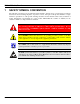
MM-011553-001, Rev. A 1 SAFETY SYMBOL CONVENTION The following conventions are used throughout this manual to alert the user to general safety precautions that must be observed during all phases of operation, service, and repair of this product. Failure to comply with these precautions or with specific warnings elsewhere in this manual violates safety standards of design, manufacture, and intended use of the product. M/A-COM, Inc.
MM-011553-001, Rev. A 2 RF ENERGY EXPOSURE INFORMATION 2.1 RF ENERGY EXPOSURE AWARENESS, CONTROL INFORMATION, AND OPERATION INSTRUCTIONS FOR FCC OCCUPATIONAL USE REQUIREMENTS Before using your mobile two-way radio, read this important RF energy awareness and control information and operational instructions to ensure compliance with the FCC’s RF exposure guidelines.
MM-011553-001, Rev. A 2.2 COMPLIANCE WITH RF EXPOSURE STANDARDS Your MA/COM, Inc. M7200 mobile two-way radio is designed and tested to comply with a number of national and international standards and guidelines (listed below) regarding human exposure to RF electromagnetic energy. This radio complies with the IEEE and ICNIRP exposure limits for occupational/controlled RF exposure environment at duty factors of up to 50% talk-50% listen and is authorized by the FCC for occupational use.
MM-011553-001, Rev. A 2.2.1 Mobile Antennas Install the radio’s antenna (refer to Table 2-1 for applicable antenna part numbers) in the center of the vehicle’s roof. These mobile antenna installation guidelines are limited to metal body motor vehicles or vehicles with appropriate ground planes. The antenna installation should additionally be in accordance with the following. 1. The requirements of the antenna manufacturer/supplier included with the antenna. 2.
MM-011553-001, Rev. A 3 OPERATION SAFETY RECOMMENDATIONS 3.1 TRANSMITTER HAZARDS The operator of any mobile radio should be aware of certain hazards common to the operation of vehicular radio transmitters. A list of several possible hazards is given: • Explosive Atmospheres – Just as it is dangerous to fuel a vehicle with the motor running, similar hazards exist when operating a mobile radio. Be sure to turn the radio off while fueling a vehicle.
MM-011553-001, Rev. A 4 OPERATING RULES AND REGULATIONS Two-way FM radio systems must be operated in accordance with the rules and regulations of the local, regional, or national government. In the United States, the M7200 mobile radio must be operated in accordance with the rules and regulations of the Federal Communications Commission (FCC). As an operator of two-way radio equipment, you must be thoroughly familiar with the rules that apply to your particular type of radio operation.
MM-011553-001, Rev. A 5 PRODUCT DESCRIPTION When operating the M7200 mobile radio in P25, EDACS®, or Conventional mode, refer to the standard M7200 operator’s manual, MM23016, available online at www.macom-wireless.com. The M7200 Vehicular Tactical Network provides public safety users extended connectivity with the most advanced digital voice and data network.
MM-011553-001, Rev. A 5.2 • Comfort settings, such as volume and display brightness that are applicable to the individual control head can be adjusted and cannot be overridden by other control heads. • An optional intercom function is available between control units. (Audio will be broadcast to ALL connected control heads.) INTERCOM OPERATION The intercom option, a licensed option, allows the M7200 radio to pass audio locally between control heads and not over the network.
MM-011553-001, Rev. A 6 OPERATION 6.1 CH721 FRONT PANEL COMPONENTS The front panel of the control head includes a dot matrix display, controls for menu navigation, an emergency button, three pre-set buttons, a Power On/Off Volume Control Knob, and a microphone connector. In addition, the system model control head features a DTMF keypad. Table 6-1 lists all default front panel controls and their functions.
MM-011553-001, Rev. A In addition, the front panel contains a light-level sensor that samples ambient light levels for automatic display and button backlight brightness adjustments. In other words, it automatically brightens the display and backlights when higher external light levels exist and it automatically dims the display and backlights during lower external light levels.
MM-011553-001, Rev. A 2. Wait for the power-up sequence to complete, which takes approximately ten (10) seconds. During this time, if enabled for auto registration, the radio is provisioned with a customized user personality designed for the user’s specific needs by the OpenSky network administrator. If this personality contains encrypted talk groups or if the user is authorized for, and intends to use, manual encryption, User Login must be performed.
MM-011553-001, Rev. A 6.5 LOG OFF THE NETWORK The *0## command de-registers the radio. Typically, this is automatically performed when powering down the radio. Using this method, the User ID is remembered by the radio so only the password is needed at next log-in. Manually log-off by pressing *0## (requires System Model). If a user is logged in using encryption features, it is necessary to log-off when encryption is no longer required. 6.
MM-011553-001, Rev. A 6.8 RADIO STATUS ICONS Status Icons indicate the various operating characteristics of the radio. The icons show operating modes and conditions (see Table 6-2). The location of icons on the display may vary depending on configuration. Table 6-2: Icons and Descriptions ICON DESCRIPTION Indicates data registration. Volume bars – indicates relative volume level. 6.
MM-011553-001, Rev. A Profile 1 Profile 2 Profile 3 TG a TG d TG a TG b TG e TG d TG c TG f TG g TG x TG h TG y TG i TG z TG = Talk Group Figure 6-3: Personality Structure Example 6.10.2 Talk Groups A talk group represents a set of users that regularly need to communicate with one another. There can be any number of authorized users assigned to a talk group. Talk groups are established and organized by the OpenSky network administrator.
MM-011553-001, Rev. A NAME TONE DESCRIPTION Emergency Cleared Tone one long low-pitched tone Selective Call Ring Tone a ringing tone similar to a telephone PSTN Ring Tones a single medium-pitch reiterative tone. V-TAC On Tone a quick high-low-high-lowpitched beep. V-TAC Client Attach/Detach Tone a quick high-pitched beep. This tone sounds when a portable radio (“client”) attaches to or detaches from the V-TAC.
MM-011553-001, Rev. A Table 6-4: Basic Menu Structure Menu Name Radio Displays (top and bottom lines) Usage Notes To/From Dwell Display Engineering Display (Menu may not be available per programming.) registration, RF sync and transceiver status codes Displays radio system connection data. For engineering use. bit-error rates and RSSI data Silent Emergency OFF/ON “SilentEmerg” Operating Mode available modes “Mode Menu” Use to choose an available mode. Press MENU and and press MENU again.
MM-011553-001, Rev. A Menu Name Radio Displays (top and bottom lines) Usage Notes See Previous Page Intercom “ON” or “OFF” “INTERCOM” Selected Channel selected channel (Menu may not be available per radio programming) “ChannelMenu” Displays the current channel. Press MENU to return to dwell display. Scan Mode current scan mode “ScnModeMenu” Use to turn scan on and off. Press MENU to return to dwell display.
MM-011553-001, Rev. A Menus and button function will vary depending upon system programming, radio hardware, and optional configurations. No V-TAC-related menus are displayed on non-V-TAC radios/control heads. The “Vchan Menu” is only displayed if the V-TAC is in the SOI mode. If a V-TAC is in an Extended Coverage mode (XCOV or XCOV-TG), the number of portable radios (“clients”) connected to the V-TAC is displayed in the bottom line of the dwell menu.
MM-011553-001, Rev. A 6.14.1 Password Entry Password entry requires a system model control head. Password characters are encrypted on the display using symbols to indicate the entry. The encryption symbols for each entry will appear in the display as they are scrolled through, for example: '-' and '+'. Press the # key twice to complete the entry process. If the password is wrong, the radio will not successfully register with the network for wide area voice reception.
MM-011553-001, Rev. A 6.17 ADJUSTING DISPLAY & BUTTON BACKLIGHT BRIGHTNESS The radio uses a light sensor on the front panel to automatically adjust display brightness and button backlight brightness to ambient light conditions. The display and backlights automatically brighten at higher external light levels and automatically dim at lower external light levels. However, the “Bright Menu” gives the user some manual brightness control as follows: 1.
MM-011553-001, Rev. A If the radio is operating properly but side tones are not heard when the menu buttons are pressed, the side tones are probably turned off. To turn them back on, access the “Side Tone” menu and select a setting other than “off.” Use the following procedure set side tone level: 1. Use display. to cycle through the menu until the “Side Menu” appears in the bottom line of the 2. Use to change to the desired level (Off, Low, Medium, and High).
MM-011553-001, Rev. A 6.21.2 Transmitting a Voice Call Transmit a voice call as follows: 1. Turn the radio on. 2. If required, log-in to the network using a user ID and password. See Section 6.4 beginning on page 16 as necessary. 3. Select the desired talk group for transmitting on. 4. Depress and hold the Push-to-Talk (PTT) button on the hand-held microphone, pause for a moment, and then speak normally.
MM-011553-001, Rev. A CAUTION A user at a radio with only one control head/front panel can turn intercom mode on. In this case, pressing the microphone’s PTT button will not send microphone audio anywhere. 6.24 TALK GROUP LOCK OUT There are two ways of focusing voice communications by suppressing calls from talk groups in the currently active profile: 1. No Scan. By turning scan off (selecting “No Scan” via the “ScnModeMenu”), only the selected talk group is audible. 2. Lock Out.
MM-011553-001, Rev. A 6.24.2 Unlock a Talk Group 1. Use to scroll through the menu until “LockOutMenu” appears in the bottom line of the display. The name of a talk group in the currently active profile will appear in the top line. 2. Use to scroll through the list of talk groups, if any, until the talk group desired for unlocking appears in the top line of the display. A less-than symbol (“<”) appears next to the name of a talk group that is currently locked out. 3.
MM-011553-001, Rev. A 1. Use to scroll through the menus until “ScnModeMenu” appears in the display. 2. Use to scroll through the scan options until the desired mode appears. See Table 6-6. 6.25.2 Scanning Priority The following lists the scanning priority order (from highest to lowest): 1. Selected talk group in emergency state. 2. Default emergency group in emergency state. 3. Selected talk group. 4. Emergency capable group in emergency state 5. Priority 1 talk group. 6. Priority 2 talk group. 7.
MM-011553-001, Rev. A 2. Enter the number of the radio to be called (e.g., 027-001-0006). If the region number (first 3 digits; 027 in this example) is the same as this radio’s region number, these digits do not need to be entered. Likewise, if the region and agency numbers (first 6 digits; 027-001 in this example) are the same as this radio’s numbers, these digits do not need to be entered. Leading zeros can also be ignored. 3. Press and release the # key. 4. Wait approximately two (2) seconds. 5.
MM-011553-001, Rev. A destination (receiving) radio. The sending radio receives a brief message noting the status of the transmission. Refer to Table 6-7 for a list of possible status messages. The first few characters of a message are part of the message text entered when the message is programmed. This programming is performed by the system or network administration personnel. Messages successfully received by the destination radio are stored in it until read or until it is power cycled. 6.27.
MM-011553-001, Rev. A Table 6-7: Status of Selective Alert STATUS MESSAGE 6.27.
MM-011553-001, Rev. A 2. Enter the telephone number. (Ignore dashes/spaces, and precede the number with any required access digits such as a 1 for long distance.) 3. Press the # key. 4. Wait a few seconds and then press and release the mic’s PTT button to initiate the call. An initial ring tone plays indicating call initiation. Once the gateway picks up the call, the ring tone changes. 5. When the caller answers, depress the PTT button when speaking and release it to listen to the caller. 6.
MM-011553-001, Rev. A 6.29.2 Silent Emergency When this feature is enabled and an emergency call or alert is declared by pressing the emergency button, the radio will not play a tone and will display an abbreviated emergency message (default is EBA). This feature is enabled or disabled via programming or via the menu. If the Silent Emergency feature is enabled or disabled via programming, the setting will survive power cycle.
MM-011553-001, Rev. A • An emergency call can be dismissed as described in the following section. A radio declaring an emergency on a talk group has a “hot” mic time period of typically ten (10) seconds just after it declares the emergency. This time period may be adjusted by system or network administration personnel on a per radio basis. 6.29.5 Dismissing an Emergency Call An emergency is dismissed for a configurable amount of time only (default = 5 minutes).
MM-011553-001, Rev. A If a secure call is in progress elsewhere and the user has not logged in, the bottom of the dwell display will alternate between “No Access” and the alias of the radio that is currently engaged in the secure call. 6.30.2 Manual Encryption (System Model) Two or more users can manually encrypt a call, if enabled, without an established encrypted talk group. A pre-determined key is required at each radio.
MM-011553-001, Rev. A • Lockouts • Scan mode • Intercom mode Presets are saved and restored to/from non-volatile memory. Changing the User ID (login in as a different user) will clear the presets since they are stored on a per-user basis. Changing control heads will not recall presets for the previous control head. Preset button C can be configured via programming to reboot the radio into a particular application mode.
MM-011553-001, Rev. A • Scene-of-Incident (display reads: “SOI”) • Mobile-Only (display reads: “Mobile”) These modes are described in detail in the following subsections. 6.34.1 Extended Coverage Modes (“XCOV” & “XCOV-TG”) General Information In addition to all standard mobile radio operating capabilities, Extended Coverage adds the V-TAC’s bridging (vehicular repeat) functionality for accessing the OpenSky radio network using connected portable radios.
MM-011553-001, Rev. A Operating the V-TAC in an Extended Coverage mode when the vehicle is in motion can have serious consequences to system operation and performance and is therefore not recommended. This condition is sometimes referred to as a “rolling V-TAC.” CAUTION If necessary, contact the local administrator and/or radio installation personnel for mode selection information for a particular installation.
MM-011553-001, Rev. A 6.34.2 V-TAC GPS Interlock The V-TAC GPS Interlock feature is enabled or disabled through programming by the system administrator. If enabled, the V-TAC can transition from XCOV or XCOV-TG to the Mobile Radio mode of operation based on the location and velocity of the VTAC (provided by GPS) in order to prevent a rolling VTAC. The distance and velocity required for transition are programmed by the system administrator.
MM-011553-001, Rev. A When using the SOI mode, both the V-TAC and any connected portable or mobile radios (the clients) are off the OpenSky network. Therefore, communications with radios and dispatch personnel on the network is not possible. Use the SOI mode only when absolutely necessary and only when its use is approved by an OpenSky radio system network administrator and/or a scene commander. CAUTION SOI mode employs 2-slot TDMA technology that is not synchronized to the OpenSky radio network.
MM-011553-001, Rev. A 4. Press the Select button. 5. If the SOI mode was selected, the “Vchan Menu” automatically appears; choose a radio frequency , and confirm by pressing the Select button. If selecting the SOI mode, observe channel using the WARNING in Section 6.34.3. Instead of using the “Vmode Menu,” some radio installations may be configured to automatically enter a V-TAC mode when a dash-mounted switch is flipped or some other action is performed.
MM-011553-001, Rev. A 7 BASIC TROUBLESHOOTING If the radio is not operating properly, check Table 7-1 for likely causes. For additional assistance, contact a qualified service technician. Table 7-1: Basic Troubleshooting SYMPTOM SOLUTION Radio will not turn on. No power. Test the connection to the vehicle power supply. Radio will not turn off. If in multiple control head configuration, one of the attached control heads is still powered up. Power off all control heads.
MM-011553-001, Rev. A SYMPTOM CAUSE SOLUTION Radio control head is unable to communicate with mobile radio unit (radio transceiver). Have the radio connections checked by an authorized technician. Radio authentication of the VNIC failed. Contact system administrator. VNIC authentication of the radio failed. Contact system administrator. The voice authentication security policy is set to only allow authenticated users. Contact system administrator. Control head randomly changes display.
MM-011553-001, Rev. A 8 TECHNICAL ASSISTANCE The Technical Assistance Center's (TAC) resources are available to help with overall system operation, maintenance, upgrades and product support. TAC is the point of contact when answers are needed to technical questions. Product specialists, with detailed knowledge of product operation, maintenance and repair provide technical support via a toll-free (in North American) telephone number. Support is also available through mail, fax and e-mail.
MM-011553-001, Rev. A 9 WARRANTY A. M/A-COM, Inc. (hereinafter "Seller") warrants to the original purchaser for use (hereinafter "Buyer") that Equipment manufactured by or for the Seller shall be free from defects in material and workmanship, and shall conform to its published specifications. With respect to all non-M/A-COM Equipment, Seller gives no warranty, and only the warranty, if any, given by the manufacturer shall apply.
Tyco Electronics Wireless Systems Segment 221 Jefferson Ridge Parkway Lynchburg, Virginia 24501 (Outside USA, 1-434-385-2400) Toll Free 1-800-528-7711 www.macom-wireless.com Printed in U.S.A.