Operator’s Manual MM23772 Rev.
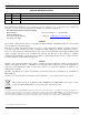
MM23772, Rev. B MANUAL REVISION HISTORY REV - DATE Jan/06 REASON FOR REVISION Initial release. A Dec/06 Updated operation info. B Apr/07 Added EDACS/Conventional/P25 operation. M/A-COM Technical Publications would particularly appreciate feedback on any errors found in this document and suggestions on how the document could be improved. Submit your comments and suggestions to: Tyco Electronics Wireless Systems Segment M/A-COM, Inc.
MM23772, Rev. B TABLE OF CONTENTS Page 1 SAFETY CONVENTIONS..................................................................................................................10 2 SAFETY TRAINING INFORMATION ............................................................................................11 2.1 RF EXPOSURE GUIDELINES .................................................................................................11 2.2 ELECTROMAGNETIC INTERFERENCE/COMPATIBILITY..................................
MM23772, Rev. B TABLE OF CONTENTS 7.10 7.11 7.12 7.13 7.14 7.15 7.16 7.17 7.18 7.19 7.20 7.21 7.22 7.23 7.24 7.25 7.26 7.27 7.28 7.29 4 Page 7.9.1 Display’s Top Line ........................................................................................................30 7.9.2 Display’s Second Line...................................................................................................30 7.9.3 Dwell Display ..............................................................................
MM23772, Rev. B TABLE OF CONTENTS Page 8 EDACS OPERATION..........................................................................................................................48 8.1 TURNING ON THE RADIO .....................................................................................................48 8.2 CONTROLS ...............................................................................................................................48 8.2.1 Buttons and Knobs..................................
MM23772, Rev. B TABLE OF CONTENTS 8.24 8.25 8.26 8.27 8.28 8.29 9 6 Page TELEPHONE INTERCONNECT CALLS ................................................................................71 8.24.1 Receiving a Telephone Interconnect Call......................................................................71 8.24.2 Sending a Telephone Interconnect Call .........................................................................71 8.24.3 Dual-Tone Multi-Frequency: Overdial/Conventional Mode ....................
MM23772, Rev. B TABLE OF CONTENTS 9.18 9.19 9.20 Page 9.17.2 Digital Mode..................................................................................................................90 9.17.3 Private Mode..................................................................................................................91 9.17.4 Private Operation...........................................................................................................92 GROUP CALLS IN P25 MODE .......................
MM23772, Rev. B TABLE OF CONTENTS Page 12 BASIC TROUBLESHOOTING........................................................................................................113 FIGURES Figure 4-1: Removing the Battery Pack......................................................................................................... 17 Figure 4-2: Attaching the Battery Pack..........................................................................................................
MM23772, Rev. B TABLE OF CONTENTS Page Table 7-2: Status Icons Descriptions ............................................................................................................. 27 Table 7-3: Alert Tones ................................................................................................................................... 31 Table 7-4: Basic P7200 OpenSky Menu Structure ........................................................................................
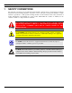
MM23772, Rev. B 1 SAFETY CONVENTIONS The following conventions are used throughout this manual to alert the user to general safety precautions that must be observed during all phases of operation, service, and repair of this product. Failure to comply with these precautions or with specific warning elsewhere in this manual violates safety standards of design, manufacture, and intended use of the product. M/A-COM, Inc. assumes no liability for the customer’s failure to comply with these standards.
MM23772, Rev. B 2 SAFETY TRAINING INFORMATION The M/A-COM P7200 portable radio generates RF electromagnetic energy during transmit mode. This radio is designed for and classified as “Occupational Use Only,” meaning it must be used only during the course of employment by individuals aware of the hazards and the ways to minimize such hazards. This radio is NOT intended for use by the “General Population” in an uncontrolled environment.
MM23772, Rev. B the recipients of your transmission, M/A-COM recommends you hold the microphone at least 5 cm (2 inches) from mouth, and slightly off to one side. Table 2-1: RF Exposure Compliance Testing Distances TESTED DISTANCES (worst case scenario) RADIO FREQUENCY 700/800 MHz Body Face 1.1 cm 2.
MM23772, Rev. B 3 OPERATING TIPS Antenna location and condition are important when operating a portable radio. Operating the radio in low lying areas or terrain, under power lines or bridges, inside of a vehicle or in a metal framed building can severely reduce the range of the unit. Mountains can also reduce the range of the unit. In areas where transmission or reception is poor, some improvement may be obtained by ensuring that the antenna is vertical.
MM23772, Rev. B 3.1.3 Aircraft Always turn off a portable radio before boarding any aircraft! Use it on the ground only with crew permission. DO NOT use while in-flight!! 3.1.4 Electric Blasting Caps To prevent accidental detonation of electric blasting caps, DO NOT use two-way radios within 1000 feet of blasting operations. Always obey the "Turn Off Two-Way Radios" signs posted where electric blasting caps are being used. (OSHA Standard: 1926.900) 3.1.
MM23772, Rev. B 4 BATTERIES The P7200 series portable radios use rechargeable, recyclable Nickel Cadmium (NiCd) or Nickel Metal Hydride (NiMH) batteries. Please follow the directions below to maximize the useful life of each type of battery. If the battery is ruptured or is leaking electrolyte that results in skin or eye contact with the electrolyte, immediately flush the affected area with water.
MM23772, Rev. B 4.2 CHARGING BATTERY PACKS Battery chargers are available from M/A-COM with nominal charge times of one hour. Combinations include single and multi-position, rapid charge units. M/A-COM chargers are rapid chargers specifically designed for charging nickel-based battery packs. The chargers differentiate between NiCd or NiMH battery packs and automatically adjust charging rates. Refer to the appropriate charger manual for specific operating instructions. 4.2.
MM23772, Rev. B 4.4 CHANGING THE BATTERY PACK 4.4.1 Removing the Battery Pack Make sure the power to the radio is turned OFF. CAUTION Although the P7200 has been designed to tolerate changing the battery pack without turning power off, M/A-COM, Inc. recommends turning the radio off before changing battery packs to ensure safety and best operation. 1. Press the latch at the bottom of the battery pack. 2. Lift the battery pack from the bottom. 3. Remove the battery pack from the radio.
MM23772, Rev. B 4.5 BATTERY DISPOSAL In no instance should a battery be incinerated. Disposing of a battery by burning will cause an explosion. CAUTION RECHARGEABLE BATTERY PACK DISPOSAL – The product you have purchased contains a rechargeable battery. The battery is recyclable. At the end of its useful life, under various state and local laws, it may be illegal to dispose of this battery into the municipal waste stream.
MM23772, Rev. B 5 INTRODUCTION The P7200 series radios are dual-band multi-mode portable radios. The P7200 series radio is available without a front mounted keypad (P7230 Select model - Figure 5-1), with a 6-buttoned front mounted keypad (P7250 Scan model - Figure 5-2) and with a DTMF front mounted keypad (P7270 System model Figure 5-3). The dual-band (700/800 MHz) P7200 portable radio delivers end-to-end encrypted digital voice and IP data communications.
MM23772, Rev.
MM23772, Rev. B Figure 5-3: P7270 “System” Model 5.1 WATER RESISTANCE The P7200 series portable radios operate reliably even under adverse conditions. These radios meet MILSTD-810F specifications for driven rain, humidity, and salt fog. 5.2 UNIVERSAL DEVICE CONNECTOR (UDC) The Universal Device Connector (UDC) provides connections for external accessories such as a headset or a speaker-microphone and for programming cables. The UDC is located on the right side of the radio (opposite the PTT Button).
MM23772, Rev. B 6 OPTIONS AND ACCESSORIES Table 6-1 lists the Options and Accessories tested for use with the P7200 series portable radios. Refer to the maintenance manual or to M/A-COM’s Products and Services Catalog for a complete list of options and accessories, including those items that do not adversely affect the RF energy exposure. Always use M/A-COM authorized accessories (antennas, batteries, belt clips, speaker/mics, etc).
MM23772, Rev.
MM23772, Rev. B 7 OPENSKY OPERATION Once an OpenSky system has been selected from the available systems on your P7200 series portable radio, the characteristics described in the following sections will govern operation. 7.1 POWER ON/OFF AND VOLUME CONTROL 7.1.1 Power ON/OFF Rotate the Power ON/OFF/Volume Control knob clockwise to power the radio on and counter-clockwise to power the radio off. The radio will begin the Startup/Log On/Provision/Self-Test sequence and register on the OpenSky network.
MM23772, Rev. B 7.2.1 Buttons and Knobs The function of the button and knob controls will vary depending on the mode of operation. The primary functions of the button and knob controls when in the OpenSky mode of operation are listed in the following paragraphs. POWER ON-OFF VOLUME KNOB Applies power to the radio and adjusts audio volume. Rotating the control clockwise applies power to the radio. A single alert tone (if enabled through programming) indicates the radio is operational.
MM23772, Rev. B 7.2.2 Keypad (P7250 and P7270 Only) The keys on the keypad have special functions and are labeled using a symbol or abbreviated word describing its primary function. Numeric entry is a secondary function of the keys. Each key is described in the following subsections. Table 7-1: Keypad Functions KEY FUNCTION Primary function: Acts much as an “enter” button to activate a selection.
MM23772, Rev. B 7.3 DISPLAY The P7200 display is made up of 3 lines. Lines 1 and 2 contain twelve alpha-numeric character blocks each. The 3rd line displays radio status icons. If programmed, the display backlighting will illuminate upon power up or when operating radio controls. See the operation sections of this manual for specific display characteristics. Figure 7-2: Blank Radio Display 7.4 RADIO STATUS ICONS Status Icons indicate the various operating characteristics of the radio.
MM23772, Rev. B 7.5 TRI-COLOR LED Figure 7-3: Tri-Color LED The Tri-Color LED changes color to indicate radio status and is visible from both the front and top of the radio (see Figure 7-3). In OpenSky mode only two radio states are reflected by the LED and the status they represent are: 7.6 Green: Receiving Red: Transmitting Orange: If the LED is flashing rapidly, the radio is receiving an emergency call.
MM23772, Rev. B 7.7 LOG OFF THE NETWORK The *0## command de-registers the radio. Typically, this is automatically performed when powering down the radio. Using this method, the User ID is remembered by the radio so only the password is needed at next log-in. Manually log-off by pressing *0##. If a user is logged in using encryption features, it is necessary to log-off when encryption is no longer required. 7.
MM23772, Rev. B 7.9 OPENSKY DISPLAY OVERVIEW The 12-character x 3-line display shows the radio status. The first two lines of the display are text lines that change in response to user interaction with the menu buttons. Status icons appear in the bottom line (line 3) of the display (see Table 7-2). 7.9.1 Display’s Top Line The display’s top line of text changes as the and buttons are pressed to scroll through the available menu options (see Table 7-4).
MM23772, Rev. B 7.10 ALERT TONES The P7200 radio also provides audible Alert Tones or “beeps” to indicate the various operating conditions (see Table 7-3).
MM23772, Rev. B 7.11 BASIC MENU STRUCTURE Table 7-4 illustrates the basic P7200 OpenSky menu structure. Menu items will vary depending upon system programming, radio hardware, and optional configurations. All menus except the dwell display menu can be turned off by network administration personnel. Menu Name Table 7-4: Basic P7200 OpenSky Menu Structure Radio Displays Usage Notes (first and second lines) To/From Dwell Display Engineering Display (Menu may not be available per programming.
MM23772, Rev. B Menu Name Radio Displays (first and second lines) Usage Notes See Previous Page Scan Mode (e.g.
MM23772, Rev. B 7.12 KEYPAD FUNCTION COMMANDS (P7270 ONLY) To perform a command from the keypad, use on of the following keypad commands: Table 7-5: Keypad Function Commands *0 *1 *4 *7 *8 *9 *32 *33 *61 *62 *60 Log-off command: *0## (logs the user off the system). See Section 7.7 for additional information. Log-in command: *1 # ## (required for encryption). See Section 7.3 for additional information.
MM23772, Rev. B 7.16 STEALTH MODE For some users, it is important to be able to turn off the radio’s display lights and side tones, but not the radio traffic. For example, in covert operations, lights and sounds could inadvertently expose an otherwise unobservable radio user. For this purpose, the radio has a Stealth feature that disables the radio display light, indicator light and audible side tones.
MM23772, Rev. B 7.18 CHANGE OPERATING MODE 1. Press the or buttons to cycle through the menu until “Mode Menu” is displayed. 2. Press or to select the desired operating mode. 3. Press and use or to select Y or N. 4. Press again to make selection and return to the dwell display 7.
MM23772, Rev. B Lock out is a listening (receive) function and only blocks received calls on locked out talk groups. Lock out does not affect transmit capability. “No Scan” and “Lock Out” do not apply to recent emergency lock outs. Only talk groups in the active profile can be locked out, since they are the only talk groups whose voice calls can be heard on the radio. Talk group lock out is a scan-related feature.
MM23772, Rev. B 7.22 SCANNING 7.22.1 Selecting Scan Modes Three scanning modes are available for the radio, but only one can be active at any time. Changing the scanning mode changes the way the radio scans voice calls for all of the profiles in the radio personality, no matter which profile is or becomes active. The choice of scanning mode broadens or narrows the span of communications with all the groups in profiles you listen to, but does not affect your interaction with those groups you talk with.
MM23772, Rev. B 7.22.2 Checking or Changing Active Scan Mode 7.22.2.1 Setting the Scan Mode 1. Press the or buttons until “ScnModeMenu” appears in the display. 2. Use the or keys to scroll through the list of modes until your choice appears: Normal, None, or Fixed. 3. Press the key to activate the scan mode selection and return to the dwell display. 7.22.2.2 Duration of Scanning Mode Selections Scanning Mode selections survive power down.
MM23772, Rev. B In the OpenSky system, a radio can be configured to initiate selective calls through a pre-programmed list in memory called a speed dial list. Alternatively, a properly equipped radio can initiate a selective call to any radio in the system by entering the ten-digit User ID (similar to a telephone number) of the target radio. Some radios are configured to only receive (not initiate) selective calls. Selective calls are terminated if an emergency is declared.
MM23772, Rev. B If the other user accepts the call, the called user’s alias will appear in initiating caller’s display. The two are now in a private call until one ends the call, or the call is terminated due to an initiated emergency. If the called radio is involved in another selective call, “BUSY” will appear on the second line of the display. “Unavailable” is displayed when the call has not been answered after a 1 minute timeout or when the other party is not registered on the network. 7.23.
MM23772, Rev. B Table 7-7: Status of Selective Alert Messages STATUS MESSAGE 7.24.2 DEFINITION Delivering Select Alert message transmit attempt Busy Too busy – Try again Dest Down Receiving radio not logged on – Not registered Not Reg Transmitting radio not logged on – Not registered Delivered Transmission complete Unreachable No response Partial Transmission interrupted Sending a Message The sending process has three steps.
MM23772, Rev. B 7.24.3 Receiving a Message When a selective alert message is received by a radio, a four-beep tone is heard. The tone is heard only once, but the message “NEWALRT” alternates with the talk group on the main display. Up to 8 received messages can be stored. If a ninth message is received, the first (oldest) message is automatically deleted to make room for the new message. Received messages are displayed with the time and source information. To display a Selective Alert Message: 1.
MM23772, Rev. B Table 7-8: Emergency Calls vs. Emergency Alerts EMERGENCY ALERT EMERGENCY CALL An Emergency Alert message is sent to the dispatcher console. The dispatch console plays an emergency tone when it receives the message. An Emergency Alert message is sent to the dispatcher console. All peers (radios and consoles) and the dispatch console play the emergency tone whenever an emergency call is detected.
MM23772, Rev. B With “No Scan,” only the emergency tone is heard, not the initial open mic transmission. To dismiss or ignore the emergency, refer to Section 7.26.3. 7.26.3 Dismissing an Emergency The “Dismissing an Emergency” function allows you to “ignore” an emergency declared by another user. An emergency is dismissed for a configurable amount of time (default = 5 minutes). 1. After receiving an emergency call, press the or button until you see “EmgDismiss.” 2.
MM23772, Rev. B 7.27.1 Automatic Encryption For automatic encryption, a system administrator will select the talk group to be encrypted at the interface to the UAS. Once the talk groups have been selected and identified as secure, credentials for key generation are generated automatically by the system and provisioned to authorized users. This process requires that authorized users login to the network and be authenticated.
MM23772, Rev. B 7.28 DYNAMIC REGROUPING Dynamic regrouping requires that the network administrator determine which radio users should be formed into an impromptu talk group to respond to particular emergency conditions. The administrator will edit the personalities of the affected radios to include an emergency profile and then page the affected radios to re-register with the network to receive their edited personalities.
MM23772, Rev. B 8 EDACS OPERATION 8.1 TURNING ON THE RADIO 1. Power ON the radio by rotating the POWER ON-OFF/VOLUME knob clockwise. A short alert signal (if enabled through programming) indicates the radio is ready to use. Refer to Figure 8-1 for location of the POWER ON-OFF/VOLUME KNOB. 2. The display shows the last selected system and group or a default system and group (depending on programming). 3. Adjust the POWER ON-OFF/VOLUME knob to the desired volume level. 4.
MM23772, Rev. B 8.2.1 Buttons and Knobs This section describes the primary function of the button and knob controls. Other functions associated with these controls are detailed in later sections. POWER ON-OFF VOLUME KNOB Applies power to and adjusts the receiver’s volume. Rotating the control clockwise applies power to the radio. A single alert tone (if enabled through programming) indicates the radio is operational. Rotating the control clockwise increases the volume level.
MM23772, Rev. B 8.2.2 Keypad (P7250 “Scan” and P7270 “System” Models Only) The keys on the keypad have special functions and are labeled using a symbol or abbreviated word describing its primary function. Numeric entry is a secondary function of the keys. Each key is described in the following subsections. Figure 8-2: P7250 “Scan” Radio Front Panel KEY FUNCTION Primary Function: Allows the user to scroll through available systems, groups, or channels, depending on personality programming.
MM23772, Rev. B Figure 8-3: P7270 “System” Radio Front Panel KEY FUNCTION Primary Function: Allows the user to scroll through available systems, groups, or channels, depending on personality programming. Secondary Function: Changes the selection for an item within a list. Primary Function: Accesses the pre-stored menu. Secondary Function: Activates a selected item within the menu. This is similar to an “Enter” key. Selects a specific system.
MM23772, Rev. B 8.3 DISPLAY The radio Display is made up of 3 lines (see Figure 8-4). Lines 1 and 2 contain eight alphanumeric character blocks and are used primarily to display system and group names. Line 1 also displays radio status messages. The 3rd line is used primarily to display radio status icons. All three lines are used to display menu options when in the menu mode. If programmed, the display backlighting will illuminate upon power up or when radio controls are operated.
MM23772, Rev. B 8.4 RADIO STATUS ICONS Status Icons indicate the various operating characteristics of the radio. The icons show operating modes and conditions and appear on the third line of the display (see Table 8-1). The battery icon indicates approximate level only, based on battery voltage.
MM23772, Rev. B 8.5 TRI-COLOR LED Figure 8-5: Tri-Color LED The Tri-Color LED changes color to indicate radio status and is visible from both the front and top of the radio (see Figure 8-5). The three colors of the LED and the status they represent are: 8.6 Green: Receiving Red: Unencrypted transmission Orange: Encrypted transmission STATUS MESSAGES During radio operation, various radio Status Messages can be displayed. The messages are described below.
MM23772, Rev. B 8.7 MESSAGE NAME DESCRIPTION TXEMER Transmit Emergency Indicates an emergency call has been transmitted on this radio. This message will be flashing on line two. VOL=31 Volume Level Indicates the current volume level. The volume level display ranges from OFF (silent) to 31 (loudest). WHC Who Has Called Indicates an individual call has been received, but not responded to.
MM23772, Rev. B 8.9 SYSTEM SELECTION METHOD 1: From the control knob: If system selection is programmed to the SYSTEM/GROUP/CHANNEL SELECTION control knob, select a system by turning the knob to the desired system number position (1-16). The display registers the new system name on line one.
MM23772, Rev. B METHOD 2: (System and Scan model radios only) From keypad: If group selection is programmed as the primary function of and select a group by pressing or to scroll through the group list. The display registers the new group name on line two. METHOD 3: (System model radios only) Direct Access: Press to enter the group select mode. Press the numeric key mapped to the desired group. Press . The radio will move to the selected group.
MM23772, Rev. B 8.12 NUISANCE DELETE (SYSTEM MODEL) A channel can temporarily be deleted from the scan list if it is not the currently selected channel. 1. Turn Scan ON. 2. When the radio receives a call on the channel, press the list until the radio is power cycled. . The channel is removed from the scan 8.13 BACKLIGHT ON/OFF 1. Press to access the menu. 2. Press to scroll through menu until “BCKLGHT” appears. 3. Press to select Backlight menu. 4. Press or to toggle backlight ON and OFF. 5.
MM23772, Rev. B 8.17 HIGH/LOW POWER ADJUSTMENT Transmit power adjustment is possible if enabled through programming. Within conventional systems, transmit power is adjustable on a per channel basis. Within EDACS systems, transmit power is adjustable on a per system basis. There are two ways to toggle between high and low power: 8.17.1 Using the Menu Button 1. Press . 2. Using the display. and keys, scroll until the cursor (>) appears to the left of “TX POWER” in the 3.
MM23772, Rev. B 8.18.1 Menu Item Selection Process An example of the menu item selection process and menu item parameter change is detailed below for the backlight menu item. 1. Press . The menu mode is entered. 2. Press or until the display shows: 3. Press . The backlight menu item is activated. Line one shows the active menu item and its current parameter setting. Line two shows the currently selected system or group name (see Figure 8-7). Figure 8-7: Backlight Menu Display 4.
MM23772, Rev. B FEATURE PARAMETER SETTING DISPLAY COMMENT Transmit Power Select Menu Item: HIGH or LOW TX POWER Once Selected: POWER= N/A Radio Revision Menu Item: Information REVISION Selects radio output power mode.
MM23772, Rev. B 8.19 DIGITAL VOICE OPERATION Digital voice programmed systems have three (3) different voice modes: clear (analog), digital, and private (encrypted). The voice modes are programmed on a per-group basis within each trunked system. 8.19.1 Clear Mode The Clear Mode is a voice mode in which the radio transmits and receives only clear (analog) voice signals. These analog signals are non-digitized and non-encrypted. Clear mode transmissions can be monitored easily by unauthorized persons.
MM23772, Rev. B 8.19.3.1 Displaying the Currently Used Cryptographic Key Number To Display the Currently Used Cryptographic Key Number for either the system encryption key (for special call such as individual, phone, all, agency or fleet) or the group/channel key (for group or conventional calls), perform the following procedure: 1. Press the button. 2. Use the or button to select "DISP KEY." 3.
MM23772, Rev. B 8.19.4.2 Transmitting an Encrypted Call 1. Select the desired group or channel. 2. Place the radio in Private Mode by pressing key, and then follow the selection mode rules. On a System radio, the key can be used to toggle the Private Mode ON/OFF. When Private Mode is enabled, the icon is displayed. If the last state of the radio was Private Mode, the Private Mode will be enabled on power up. Also, the Private Mode will be enabled if forced operation has been programmed in the radio.
MM23772, Rev. B • If the radio scans to a group other than the selected group then receives a call on the selected group, the radio will switch to the selected group. However, if the “scanned-to” group is programmed at a higher priority the radio will remain on the “scanned-to” group. • The radio will continue scanning if a new group is selected when scan is ON. 3.
MM23772, Rev. B 4. Press a second time to set the group to Priority 2. A is displayed on line three. 5. Press a third time to set the group to Priority 1. A is displayed on line three. The priority level selection sequence only advances the group to next higher priority level and stops at priority level 1. To select a lower priority level, the group must be deleted from the scan list and then added back to the scan list. Each new group added to the scan list starts at the lowest priority.
MM23772, Rev. B 8.21 SCANNING TRUNKED SYSTEMS The radio can be programmed with the following System Scan features. These features are automatically enabled when the radio is powered ON. A key or menu option is also defined to allow the System Scan features to be toggled during radio operation. The System Scan state will be maintained through system changes but will default to ON when the radio is powered ON.
MM23772, Rev. B signal quality of the control channel for each site in its adjacent scan list. (The signal quality metric used for the ProScan algorithm is based on a combination of both Received Signal Strength Indicator (RSSI) and Control Channel Verification (CCV) measurements.) When the selected system degrades to a preprogrammed level, the radio will begin to look for a better control channel.
MM23772, Rev. B The volume of the ring is adjustable through the volume control levels. If a response is made by pressing the PTT to the call prior to the programmed call-back time-out, the call will automatically be directed to the originating unit. If a response is not made before the call-back timeout, the radio will return to normal receive display, and *WHC* will appear on the first line of the LCD. To respond after the call-back time-out, press the key.
MM23772, Rev. B 8.23.2 Sending an Individual Call 8.23.2.1 Pre-Stored Individual Calls The following procedures describe how to initiate and complete a Pre-Stored Individual Call. System Model Radio: 1. To select a pre-stored individual phone number, enter the individual call mode using the key. displayed. Then scroll through the list of stored numbers using the or key. is 2. Press the PTT button; when the radio is clear to transmit, turns ON, turns OFF and the channel access tone sounds.
MM23772, Rev. B Figure 8-12: Calls Received and Personality Lists The saved call list shows all ten storage locations. If no calls have been received, the saved call list will be empty and the pre-stored list will be available upon entering the individual call mode. When in the saved call list, pressing the key toggles the time stamp ON and OFF. The time stamp indicates how long ago the call was received. When in the pre-stored list pressing the key toggles the Logical IDentification (LID) ON and OFF.
MM23772, Rev. B until the special call is cleared or the time-out expires or another group or system is selected. Terminate a call by pressing the button. In half-duplex mode, only one person may talk at a time. The radio PTT button needs to be pressed in order to communicate to the individual called and released for the individual called to be heard. 8.24.2.2 Direct Dialing of Phone Calls (System Model Only) 1.
MM23772, Rev. B select/entry mode remains active until the call is dropped, cleared, or is pressed. The overdial select/entry mode can be re-entered if the call is still active by pressing . P7270 Model Radio: 1. Follow the procedure in Section 8.24.2 to establish a connection to the telephone system or consult the system administrator for the procedure to access a dial tone on the trunked or conventional system. 2.
MM23772, Rev. B expires or the key has been pressed (the key will override the time-out period), the status is selected and will be transmitted to the site or stored in the radio memory where it can be polled by the site at a future time. Status messages can also be programmed for single key operation so that a single press of a key assigned to a status message automatically transmits that message. If the site does not receive the status properly, the radio will sound a low pitched tone.
MM23772, Rev. B time; however, either data or voice is selected transparently by the operator through normal usage of the radio. Data communications is not supported in the conventional mode. The radios can be connected to Mobile Data Terminals (MDT) or to a host computer. Any RS-232 compatible device that supports the Radio Data Interface (RDI) protocol (Version 1.91 or greater) may be connected to the radio. Support for MDTs or host computers is a programmable option per radio.
MM23772, Rev. B 8.29.5 Scan Lockout Mode Following the transmission or reception of a data call, if scan is enabled, scanning will stop temporarily (two independent pre-programmed times; after a receive data call and after a transmit data call). During this time the scan indicator will flash to indicate that scan is enabled but temporarily suspended.
MM23772, Rev. B 9 PROJECT 25 (P25) CONVENTIONAL OPERATION 9.1 TURNING ON THE RADIO Power ON the radio by rotating the POWER ON-OFF/VOLUME knob clockwise. A short alert signal (if enabled through programming) indicates the radio is ready to use. Refer to Figure 9-1 for location of the POWER ON-OFF/VOLUME KNOB. The display shows the last selected system and group or a default system and group (depending on programming). Adjust the POWER ON-OFF/VOLUME knob to the desired volume level.
MM23772, Rev. B 9.2.1 Buttons and Knobs This section describes the primary function of the button and knob controls. Other functions associated with these controls are detailed in later sections. POWER ON-OFF VOLUME KNOB Applies power to and adjusts the receiver’s volume. Rotating the control clockwise applies power to the radio. A single alert tone (if enabled through programming) indicates the radio is operational. Rotating the control clockwise increases the volume level.
MM23772, Rev. B 9.2.2 Keypad (P7250 “Scan” and P7270 “System” Models Only) The keys on the keypad have special functions and are labeled using a symbol or abbreviated word describing its primary function. Numeric entry is a secondary function of the keys. Each key is described in the following subsections. Figure 9-2: P7250 “Scan” Radio Front Panel KEY FUNCTION Primary Function: Allows the user to scroll through available systems, groups, or channels, depending on personality programming.
MM23772, Rev. B Figure 9-3: P7270 “System” Radio Front Panel KEY FUNCTION Primary Function: Allows the user to scroll through available systems, groups, or channels, depending on personality programming. Secondary Function: Changes the selection for an item within a list. Primary Function: Accesses the pre-stored menu. 1-9, *, 0, # 80 Secondary Function: Activates a selected item within a list. This is similar to an “Enter” key. Selects a specific system.
MM23772, Rev. B 9.3 DISPLAY The radio Display is made up of 3 lines (see Figure 9-4). Lines 1 and 2 contain eight alphanumeric character blocks and are used primarily to display system and group names. Line 1 also displays radio status messages. The 3rd line is used primarily to display radio status icons. All three lines are used to display menu options when in the menu mode. If programmed, the display backlighting will illuminate upon power up or when radio controls are operated.
MM23772, Rev. B 9.3.1 Radio Status Icons Status Icons indicate the various operating characteristics of the radio. The icons show operating modes and conditions and appear on the third line of the display (see Table 9-1). The battery icon indicates approximate level only, based on battery voltage.
MM23772, Rev. B 9.4 TRI-COLOR LED Figure 9-5: Tri-Color LED The Tri-Color LED changes color to indicate radio status and is visible from both the front and top of the radio (see Figure 9-5). The three colors of the LED and the status they represent are: 9.5 Green: Receiving Red: Unencrypted transmission Orange: Encrypted transmission STATUS MESSAGES During radio operation, various radio Status Messages can be displayed. The messages are described below.
MM23772, Rev. B 9.5.1 Error Messages If either of the Error Messages shown below is displayed, the radio is programmed incorrectly or needs servicing. DSP ERR ERR=XXXX or DIG V ERR x x (PowerUp only) Where: xxxx is the error code and DSP ERR or DIG V ERR is the message. 9.6 ALERT TONES The P7200 radio provides audible Alert Tones or “beeps” to indicate the various operating conditions (see Table 9-2). Table 9-2: Alert Tones NAME 9.
MM23772, Rev. B If system selection is programmed to the SYSTEM/GROUP/CHANNEL knob, direct access to systems is not available. Press or to scroll through different sets of 16 systems each (banks) if more than 16 systems are programmed into the radio. The systems within each bank are then selectable via the SYSTEM/GROUP/CHANNEL knob as described previously in METHOD 1. Example: System: 1 = North 2 = South 3 = East 4 = West Group: 1 = Group 1 2 = Group 2 3 = Group 3 4 = Group 4 Press .
MM23772, Rev. B 4. Press once to add as a normal group or channel. 5. Press twice to add as a Priority 2 group. 6. Press three times to add as a Priority 1 group. 7. Press to re-start scanning. 9.9.2 P7250 Scan Model 1. Press to toggle scan OFF and verify is not displayed. 2. Select group or channel. 3. Press once to remove group or channel from the list. 4. Press once to add as a normal group or channel. 5. Press twice to add as a Priority 2 group. 6.
MM23772, Rev. B 9.13 DECLARING AN EMERGENCY 1. Press and hold the red Emergency/Home button (the length of time is programmable; check with the system administrator). 2. *TXEMER* flashes in the display, plus icon and will be displayed. After 2-3 seconds the transmit turns off. 3. *TXEMER* and remains until the emergency is cleared. 4. Press the PTT and reappears. 5. Release PTT when the transmission is complete. 9.14 LOCKING/UNLOCKING KEYPAD 1. Press button. 2.
MM23772, Rev. B Figure 9-6: Menu Display 3. The radio will continue to receive and transmit normally while in the menu function. 4. To scroll through the menu options use the or keys. When the required menu item has been found align the cursor with the option then press to select it. The menu item's parameter setting shown in the display can now be changed by using or to scroll through the list of parameter values. 5.
MM23772, Rev. B The TX POWER menu item, when selected, toggles LOW/HIGH power. It does not use or to scroll nor is an additional press of the button required.
MM23772, Rev. B Table 9-4: Information Display PRS - NAME XXXXXXXX Personality Name EEPR SIZ EEPROM Size RAM SIZ RAM Size FLSH SIZ Flash Size RF BAND Frequency Band HSD RATE Data Transfer Rate PRS VER Software Version DSP_ _RAM DSP Software Version FLSH - VER FLASH Software r - released, 01A - revision state M/A-COM (C) – 2004 Copyright 9.17 DIGITAL VOICE OPERATION Digital voice programmed systems have three (3) different voice modes: clear (analog), digital, and private (encrypted).
MM23772, Rev. B 9.17.3 Private Mode The Private Mode allows the radio to transmit encrypted messages and receive clear or private transmissions. The radio transmits private if the group/channel is programmed for private operation and forced operation is pre-programmed. If autoselect operation is pre-programmed and the radio is in the Private Mode, the radio transmits in the mode of the received call if the hang time is active. If no hang time is active, the radio transmits private.
MM23772, Rev. B If the cryptographic key(s) are zeroed, one or more keys must be transferred from the Keyloader into the radio before private communications may continue. 9.17.4 Private Operation 9.17.4.1 Receiving an Encrypted Call When receiving, the radio automatically switches between clear or private operation. If the transmission being received is an encrypted transmission, it will be decrypted, the icon is displayed, the receiver will unsquelch and the message will be heard in the speaker.
MM23772, Rev. B Conventional Digital or encrypted channels require Channel Guard on the channel to operate correctly. The voice coding technology embodied in this product is protected by intellectual property rights including patent rights, copyrights, and trade secrets of Digital Voice Systems, Inc. The user of this technology is explicitly prohibited from attempting to de-compile, reverse engineer, or to disassemble the Object Code, or in any other way convert the Object Code into a human-readable form.
MM23772, Rev. B 3. When the radio receives a P25 call, the radio will unmute and the ID of the transmitting radio will appear in the display. 4. Press the PTT button to respond. 5. Unanswered calls will appear in the Who Has Called (WHC) list. 9.20 EMERGENCY GROUP CALLS IN P25 MODE There is no method available for a system-wide Emergency clear. An emergency group call must be cleared on each individual radio. 9.20.1 Declaring an Emergency Group Call 1.
MM23772, Rev. B 10 CONVENTIONAL OPERATION The radio functions in the conventional mode when using conventional communications channels (nontrunked). 10.1 CONTROLS The radio features two rotary control knobs and an emergency button mounted on the top of the radio (Figure 10-1). Push-To-Talk and option buttons are mounted on the side (Figure 10-1). The front mounted keypad has no buttons on the P7230 Select model, six buttons on the P7250 Scan model, and 15 buttons on the P7270 System Radio.
MM23772, Rev. B 10.1.1 Buttons and Knobs This section describes the primary function of the button and knob controls. Other functions associated with these controls are detailed in later sections. POWER ON-OFF VOLUME KNOB Applies power to and adjusts the receiver’s volume. Rotating the control clockwise applies power to the radio. A single alert tone (if enabled through programming) indicates the radio is operational. Rotating the control clockwise increases the volume level.
MM23772, Rev. B 10.1.2 Keypad (P7250 “Scan” and P7270 “System” Models Only) The keys on the keypad have special functions and are labeled using a symbol or abbreviated word describing its primary function. Numeric entry is a secondary function of the keys. Each key is described in the following subsections. Figure 10-2: P7250 “Scan” Radio Front Panel KEY FUNCTION Primary Function: Allows the user to scroll through available systems, groups, or channels, depending on personality programming.
MM23772, Rev. B Figure 10-3: P7270 “System” Radio Front Panel KEY FUNCTION Primary Function: Allows the user to scroll through available systems, groups, or channels, depending on personality programming. Secondary Function: Changes the selection for an item within a list. Primary Function: Accesses the pre-stored menu. 1-9, *, 0, # 98 Secondary Function: Activates a selected item within a list. This is similar to an “Enter” key. Selects a specific system.
MM23772, Rev. B 10.2 DISPLAY The radio display is made up of 3 lines (see Figure 10-4). Lines 1 and 2 contain eight alphanumeric character blocks and are used primarily to display system and group names. Line 1 also displays radio status messages. The 3rd line is used primarily to display radio status icons. All three lines are used to display menu options when in the menu mode. If programmed, the display backlighting will illuminate upon power up or when radio controls are operated.
MM23772, Rev. B 10.2.1 Radio Status Icons Status Icons indicate the various operating characteristics of the radio. The icons show operating modes and conditions and appear on the third line of the display (see Table 10-1). The battery icon indicates approximate level only, based on battery voltage.
MM23772, Rev. B Green: Receiving Red: Unencrypted transmission Orange: Encrypted transmission 10.4 STATUS MESSAGES During radio operation, various radio Status Messages can be displayed. The messages are described below. MESSAGE NAME DESCRIPTION TALKARND Talkaround Indicates the radio is operating on conventional channels in talkaround mode (no repeater). LOW BATT Low Battery Battery voltage has dropped to the point to where the radio is no longer able to transmit.
MM23772, Rev. B 10.6 TURNING ON THE RADIO 1. Power ON the radio by rotating the POWER ON-OFF/VOLUME knob clockwise. A short alert signal (if enabled through programming) indicates the radio is ready to use. Refer to Figure 10-1 for location of the POWER ON-OFF/VOLUME KNOB. 2. The display shows the last selected system and group or a default system and group (depending on programming). 3. Adjust the POWER ON-OFF/VOLUME knob to the desired volume level. 4. Select the desired system and group.
MM23772, Rev. B 10.8 GROUP/CHANNEL SELECTION Several methods can be used to select a new group or channel. METHOD 1: From the control knob: If group selection is programmed to the SYSTEM/GROUP/ CHANNEL knob, select a group by turning the SYSTEM/GROUP/CHANNEL knob to the desired group number position. The display registers the new group name on line two. If the knob is moved to a position greater than the number of programmed groups, the highest programmed group will remain selected.
MM23772, Rev. B 7. Press to re-start scanning. 10.10 NUISANCE DELETE (SYSTEM MODEL) A channel can temporarily be deleted from the scan list if it is not the currently selected channel. 1. Turn Scan ON. 2. When the radio receives a call on the channel, press the list until the radio is power cycled. . The channel is removed from the scan 10.11 BACKLIGHT ON/OFF 1. Press to access the menu. 2. Press or to scroll through menu until “BCKLGHT” appears. 3. Press to select Backlight menu. 4.
MM23772, Rev. B 10.15 HIGH/LOW POWER ADJUSTMENT Transmit power adjustment is possible if enabled through programming. Within conventional systems, transmit power is adjustable on a per channel basis. There are two ways to toggle between high and low power: 10.15.1 Using the Menu Button 1. Press . 2. Using the or key, scroll until the cursor (>) appears to the left of “TX POWER” in the display. 3. Press again to toggle between High and Low power. 4.
MM23772, Rev. B 10.16.1 Menu Item Selection Process An example of the menu item selection process and menu item parameter change is detailed below for the backlight menu item. 1. Press to enter the menu mode. 2. Press or until the display shows: 3. Press . The backlight menu item is activated. Line one shows the active menu item and its current parameter setting. Line two shows the currently selected system or group name (see Figure 10-7). Figure 10-7: Backlight Menu Display 4.
MM23772, Rev.
MM23772, Rev. B Table 10-4: Information Display PRS - NAME XXXXXXXX Personality Name EEPR SIZ EEPROM Size RAM SIZ RAM Size FLSH SIZ Flash Size RF BAND Frequency Band HSD RATE Data Transfer Rate PRS VER Software Version DSP_ _RAM DSP Software Version FLSH - VER FLASH Software r - released, 01A - revision state M/A-COM (C) – 2004 Copyright 10.17 DIGITAL VOICE OPERATION Digital voice programmed systems have three (3) different voice modes: clear (analog), digital, and private (encrypted).
MM23772, Rev. B 10.17.3 Private Mode Private Mode allows the radio to transmit encrypted messages and receive clear or private transmissions. The radio transmits private if the group/channel is programmed for private operation and forced operation is pre-programmed. If autoselect operation is pre-programmed and the radio is in the Private Mode, the radio transmits in the mode of the received call if the hang time is active. If no hang time is active, the radio transmits private.
MM23772, Rev. B will begin at the start of the 2 second period and then switch to a solid tone after the keys have been zeroed. The display will indicate KEY ZERO. If the cryptographic key(s) are zeroed, one or more keys must be transferred from the Keyloader into the radio before private communications may continue. 10.17.4 Private Operation 10.17.4.1 Receiving an Encrypted Call When receiving, the radio automatically switches between clear or private operation.
MM23772, Rev. B Conventional Digital or encrypted channels require Channel Guard on the channel to operate correctly. The voice coding technology embodied in this product is protected by intellectual property rights including patent rights, copyrights, and trade secrets of Digital Voice Systems, Inc. The user of this technology is explicitly prohibited from attempting to de-compile, reverse engineer, or to disassemble the Object Code, or in any other way convert the Object Code into a human-readable form.
MM23772, Rev. B 11 TECHNICAL ASSISTANCE The Technical Assistance Center's (TAC) resources are available to help with overall system operation, maintenance, upgrades and product support. TAC is the point of contact when answers are needed to technical questions. Product specialists, with detailed knowledge of product operation, maintenance and repair provide technical support via a toll-free (in North American) telephone number. Support is also available through mail, fax and e-mail.
MM23772, Rev. B 12 BASIC TROUBLESHOOTING Use Table 12-1 as a troubleshooting guide if the radio does not operate properly. If additional assistance is required, contact a qualified service technician or call M/A-COM at 1-800-528-7711. Table 12-1: Troubleshooting SYMPTOM POSSIBLE CAUSE POSSIBLE SOLUTION Radio will not turn on Low Battery. Change the battery pack to a fully charged pack. No Audio Speaker volume is muted. Increase the volume level.
MM23772, Rev. B BATTERY WARRANTY A. M/A-COM, Inc. (hereinafter "Seller") warrants to the original purchaser for use (hereinafter "Buyer") that nickel-cadmium and nickel-metal hydride batteries supplied by Seller shall be free from defects in material and workmanship, and shall conform to its published specifications for a period of twelve (12) months from the date of purchase. B.
MM23772, Rev. B WARRANTY A. M/A-COM, Inc. (hereinafter "Seller") warrants to the original purchaser for use (hereinafter "Buyer") that Equipment manufactured by or for the Seller shall be free from defects in material and workmanship, and shall conform to its published specifications. With respect to all non-M/A-COM Equipment, Seller gives no warranty, and only the warranty, if any, given by the manufacturer shall apply.
Tyco Electronics Wireless Systems Segment 221 Jefferson Ridge Parkway Lynchburg, Virginia 24501 (Outside USA, 1-434-385-2400) Toll Free 1-800-528-7711 www.macom-wireless.com Printed in U.S.A.