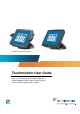
* Shown with optional peripherals Touchmonitor User Guide 1529L 15” LCD Desktop Touchmonitor, 3000 series (Optional Magnetic Stripe Reader, Barcode Scanner, Customer Display and Biometric available)
Elo TouchSystems 15” LCD Touchmonitor Optional Magnetic Stripe Reader, Customer Display, Barcode Scanner User Guide Revision G P/N 008603E Elo TouchSystems 1-800-ELOTOUCH www.elotouch.
Copyright © 2009 Tyco Electronics. All Rights Reserved. No part of this publication may be reproduced, transmitted, transcribed, stored in a retrieval system, or translated into any language or computer language, in any form or by any means, including, but not limited to, electronic, magnetic, optical, chemical, manual, or otherwise without prior written permission of Tyco Electronics. Disclaimer The information in this document is subject to change without notice.
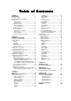
Table of Contents Chapter 1 Introduction 1 Product Description ................................................. 1 Detailed LCD Display Performance Requirements .......................................................... 2 Customer Display .............................................. 3 Serial Version ................................................. 3 Fingerprint Reader ............................................ 3 Theory of Operation ....................................... 4 Sensor Specifications .....
C H A P T E R 1 INTRODUCTION Product Description The 1529L is a retail terminal designed to present information to the operator and the customer. The 1529L is available in serial and USB versions or combo touch monitor. The 1529L consists of a 15.0” LCD main display with a touchscreen and the following optional peripherals: customer display, vacuum fluorescent display (VFD) Customer Display, fingerprint reader, barcode scanner, credit card reader, and a 6 port USB (USB version only) Hub.
The credit card reader reads all three stripes on a standard credit card or drivers license. The credit card is read by sliding the credit card, stripe side toward the display through the credit card reader forward or backward. There is a USB credit card reader only. The Hub provides 4 internal USB ports to be used by the credit card reader, the fingerprint reader or barcode scanner, the touchscreen, and the customer display.
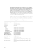
Customer Display The Customer Display is a twenty character two line vacuum fluorescent display (VFD). It consists of a VFD and VFD controller. Serial Version Optional Parameters Characters per row Number of rows Character configuration Character Height Character width Character configuration Character color MTBF 20 2 5x7 dot matrix 9.5mm 6.2mm ASCII Blue green 300,000 hours Fingerprint Reader There is a fingerprint reader in the USB version only.
Specifications Sensor Image Capture Speed Image Transfer Speed Pixel Resolution USB Signaling Type SecuGen FOR 600ms/frame 500Byte/ms 356x292 Full Speed Type Theory of Operation The USB host initiates communication with the FDU01 using operation commands (Sensor LED On, Fingerprint Capture Start and Stop). Fingerprint data are then captured by the CMOS sensor at a total image size of 356 x 292 with 8-bit gray level. The image frame transfer speed is 500 bytes/ms.
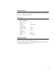
5. Effective form factor; ability to be mounted on side of ET1529L 6. USB interface that complies with USB 2.0 standards 7. USB bus powered 8. Easy communication between host and scanner 9. Visible laser diode operating at 650nm 10.600+ scans/sec 1-D scanner: 1. Ability to read 1-D codes 2. Scan angle Minimum: 47º ± 3º 3. Low cost solution 4. Effective form factor; ability to be mounted on side of ET1529L 5. USB interface that complies with USB 2.0 standards 6. USB bus powered 7.
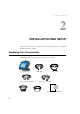
C H A P T E R 2 INSTALLATION AND SETUP This chapter discusses how to install your LCD touchmonitor and how to install Elo TouchSystems driver software.
Product Overview Main Unit Note: Shown with optional Biometric & MSR. Rear View Note: Shown with optional Rear Facing Customer Display.
Side View Base Bottom View or 2-8
TM Kensington Lock The KensingtonTM lock is a security device that prevents theft. To find out more about this security device, do to http://www. kensington.com.
USB Interface Connection Your touchmonitor comes with only one touchscreen connector cables: USB cable. (For Windows 2000, Me and XP systems only.) To set up the display, please refer to the following figures and procedures: Remove the Cable Cover The cables are connected at the back of the monitor. cable cover To remove the cover, grasp the lip of the cover and pull towards you until it snaps off.
CAUTION Before connecting the cables to your touchmonitor and PC, be sure that the computer and touchmonitor are turned off. NOTE Before connecting the cables to the touchmonitor, route all the cables through the hole in the second as shown in the picture above.
The following illustrations guide you step by step in connecting your touchmonitor using a USB cable connection. Power cord Connect one end of the power cord to the monitor and the other end to wall. Connect the power cable to the power port in the monitor.
Video cable Connect one end of the video cable to the rear side of computer and the other to the LCD. Tighten by turning the two thumb screws clockwise to ensure proper grounding. You can select DVI video cable or D-SUB15 video cable.
Speaker cable Connect one end of the speaker cable to the speaker port in the computer and the other end to the port in the monitor.
USB cable Connect one end of the USB cable to the rear side of the computer and the other to the LCD monitor. The USB cable is for optional touch, MSR, CD and Finger Print Reader. Only one USB cable is needed because the device contains a self powered USB 1.1 Hub. Two self powered ports are available for running other USB devices. For touch only, no USB Hub is present.
USB / SERIAL Interface Connection Your touchmonitor comes with only one touchscreen connector cables: USB cable. (For Windows 2000, Me and XP systems only.) To set up the display, please refer to the following figures and procedures: Remove the Cable Cover The cables are connected at the back of the monitor. cable cover To remove the cover, grasp the lip of the cover and pull towards you until it snaps off.
CAUTION Before connecting the cables to your touchmonitor and PC, be sure that the computer and touchmonitor are turned off. NOTE Before connecting the cables to the touchmonitor, route all the cables through the hole in the second as shown in the picture above.
The following illustrations guide you step by step in connecting your touchmonitor using a USB cable connection. Power cord Connect one end of the power cord to the monitor and the other end to wall. Connect the power cable to the power port in the monitor.
Video cable Connect one end of the video cable to the rear side of computer and the other to the LCD. Tighten by turning the two thumb screws clockwise to ensure proper grounding. You can select DVI video cable or D-SUB15 video cable.
Speaker cable Connect one end of the speaker cable to the speaker port in the computer and the other end to the port in the monitor.
USB cable Serial cable For USB interface, connect one end of the USB cable to the rear side of the computer and the other to the LCD monitor. For Serial interface, connect one end of the RS-232 cable to the rear side of the conputer and the other to the LCD monitor.
Replace the Cable Cover Cable cover lip cables Then you have attached all the cables to the monitor, gently bring all the cables toward the standard so they fit under the cover lip. Snap the Cable cover in place over the connections.
Optimizing the LCD Display To ensure the LCD display works well with your computer, configure the display mode of your graphic card to make it less than or equal to 1024 x 768 resolution, and make sure the timing of the display mode is compatible with the LCD display. Refer to Appendix A for more information about resolution. Compatible video modes for your touchmonitor are listed in Appendix C.
Magnetic Stripe Reader No device are needed. Testing the USB MSR Keyboard Emulation 1 Plug in the device. 2 Open MS Word. 3 Slide the card through the MSR to view the data. Testing the USB-HID Class MSR 1 On the CD, browse to Touch Monitor Peripherals\Magnetic Stripe Card Readers\Demo. 2 Open the Readme.txt and follow instructions to test the unit. Convert MSR from HID to keyboard Emulation 1 To convert from HID mode to Keyboard Emulation mode 1.
Convert MSR from keyboard emulation to HID 1 To convert from Keyboard Emulation mode to HID mode 1.1 Double-click on the “MSR Change Mode” icon on the desktop. The following will appear: 1.2 The dim box will indicate the current setting. Click the “HID Mode” to switch to HID mode. 1.3 Click “Quit” to close the window. Rear Facing Customer Display 1. Insert your Elo TouchTools CD. 2. On the CD, browse to Touch Monitor Peripherals\Rear Facing Customer Display\Drivers\USB Drivers.
Barcode Scanner 1. 2. 3. 4. Insert your Elo TouchTools CD. On the CD, browse to Touch Monitor Peripherals\Barcode Scanner Startup\Drivers. Double-click on USB7210.msi and follow the prompts given by the setup file. Once you have finished installing the above: Right click on My Computer and click on Properties. Click on the Hardware tab and then click Device Manager. 5. Double click on USB7210 Converter Module, which should be located in the Other Devices section. Next click on Reinstall Driver. 6.
2) Now scan the barcode below to change your scanning pattern. Using this scanning pattern will allow you to read 2-D barcodes (you can still read 1-D barcodes also). The scanner module also adds a Hall Effect Switch (HE Switch) that enables the unit to automatically set the Trigger mode of the Scan Engine depending on the location of an external magnet (included in scanner cradle).
Installing the Driver Software Elo TouchSystems provides driver software that allows your touchmonitor to work with your computer. Drivers are located on the enclosed CD-ROM for the following operating systems: • Windows 7 • Windows Vista • Windows XP • Windows 2000 • Windows Me • Windows 98 • Windows 95 • Windows NT 4.0 • Windows 3.1 • MS-DOS Additional drivers and driver information for other operating systems are available on the Elo TouchSystems web site at www.elotouch.com.
Installing the Serial Touch Driver (not applicable to Acoustic Pulse Recognition monitor) Installing the Serial Touch Driver for Windows 7, Windows Vista, indows XP, Windows 2000, ME, 95/98 and NT4.0. NOTE: For Windows 2000 and NT4.0 you must have administrator access rights to install the driver. Make sure the serial connector (RS232) is plugged into the monitor and an open com port on the PC. 1 Insert the Elo CD-ROM in your computer's CD-ROM drive.
C H A P T E R 3 OPERATION About Touchmonitor Adjustments Your touchmonitor will not likely require adjustment. Variations in video output and application may require adjustments to your touchmonitor to optimize the quality of the display. For best performance, your touchmonitor should be operating in native resolution, that is 1280 x 1024 at 80k-75 Hz. Use the Display control panel in Windows to choose 1280 x 1024 resolution. Operating in other resolutions will degrade video performance.
15” LCD Function Key 5 4 3 2 1 1 Controls Power Switch Function Turns the display system power on or off. 2 Select Displays the OSD menus on the screen and used to select (“Clockwise” and “Counter-clockwise” direction) the OSD control options 3 on the screen. Adjusts the decreasing value of the selected 4 OSD control option. Adjusts the increasing value of the selected OSD control option. 5 Menu Menu display and menu exit.
Controls and Adjustment OSD Lock/Unlock You are able to lock and unlock the OSD feature. The monitor is shipped in the unlocked position. To lock the OSD: 1 Press the Menu button and button simultaneously for 2 seconds. A window will appear displaying “OSD Unlock”. Continue to hold the buttons down for another 2 seconds and the window toggles to “OSD Lock”. Power Lock/Unlock You are able to lock/unlock the Power feature. The monitor is shipped in the unlockedposition.
OSD Control Options Brightness • Background Luminance of the LCD panel is adjusted. Contrast • Adjusts the contrast or the values of color gain (RED, GREEN or BLUE). Sharpness • The sharpness can be adjustable. Phase • Adjusts the phase of the dot clock. Auto Adjust • Clock system auto adjustment (under 5 seconds). OSD Left/Right • The OSD screen is moved vertically right and left. OSD Up/Down • The OSD screen is moved vertically up and down.
Power-Save (No Input) • The LCD panel background is cut when there is no signal input (AC line power consumption of 4w or less). Power LED Display & Power Saving General Power Saving Mode When the power switch are switch on, this LED lights in green. The LED indicates the different power status with altered LED colors when monitor operates in different modes (see following table). Mode On Sleep Off Power Consumption 50w max. 4w max.
CAUTION In order to protect the LCD, be sure to hold the base when adjusting the LCD, and take care not to touch the screen.
Controls and Adjustment OSD Lock/Unlock You are able to lock and unlock the OSD feature. The monitor is shipped in the unlocked position. To lock the OSD: 1 Press the Menu button and button simultaneously for 2 seconds. A window will appear displaying “OSD Unlock”. Continue to hold the buttons down for another 2 seconds and the window toggles to “OSD Lock”. Power Lock/Unlock You are able to lock/unlock the Power feature. The monitor is shipped in the unlockedposition.
OSD Control Options Brightness • Background Luminance of the LCD panel is adjusted Contrast • Gain of R, G, and B signal is adjusted. Sharpness • The sharpness can be adjustable. Phase • The phase of the dot clock is adjusted. Auto Adjust • Automatically adjusts the systems dot clock(takes approximately 5 seconds). OSD Left/Right • The osd screen is moved horizontally left and right. OSD Up/Down • The OSD screen is moved vertically up and down.
Recall Defaults • Restore all original factory defaults. OSD Timeout • Adjust how long the OSD menu is displayed. Input Video Select • Select D-SUB Analog, dvi Digital signal. Volume • To increase or decrease the sound level.
C H A P T E R 4 TROUBLESHOOTING If you are experiencing trouble with your touchmonitor, refer to the following table. If the problem persists, please contact your local dealer or our service center. Solutions to Common Problems Problem The monitor does not respond when turning on the system. Suggestion(s) 1. Check that the monitor’s Power Switch is on. 2. Turn off the power and check the monitor’s DC power cord and signal cable for proper connection.
C H A P T E R A TOUCHMONITOR SAFETY This manual contains information that is important for the proper setup and maintenance of your touchmonitor. Before setting up and powering on your new touchmonitor, read through this manual, especially Chapter 2 (Installation), and Chapter 3 (Operation). 1 To reduce the risk of electric shock, follow all safety notices and never open the touchmonitor case. 2 Turn off the product before cleaning.
Care and Handling of Your Touchmonitor The following tips will help keep your touchmonitor functioning at the optimal level. • To avoid risk of electric shock, do not disassemble the brick power supply or display unit cabinet. The unit is not user serviceable. Remember to unplug the display unit from the power outlet before cleaning. • Do not use alcohol (methyl, ethyl or isopropyl) or any strong dissolvent. Do not use thinner or benzene, abrasive cleaners or compressed air.
C H A P T E R B TECHNICAL SPECIFICATIONS B-42
Touchmonitor Specifications Model LCD Display 1529L 15.0” TFT Active Matrix Panel Display Size Pixel Pitch 304.1(H) x 228(V) mm 0.297(H) x 0.
15” LCD Touchmonitor(1529L) Dimensions 15” LCD Touchmonitor(1529L) Dimensions B-44
REGULATORY INFORMATION I. Electrical Safety Information: A) Compliance is required with respect to the voltage, frequency, and current requirements indicated on the manufacturer’s label. Connection to a different power source than those specified herein will likely result in improper operation, damage to the equipment or pose a fire hazard if the limitations are not followed. B) There are no operator serviceable parts inside this equipment.
D) General Information to all Users: This equipment generates, uses and can radiate radio frequency energy. If not installed and used according to this manual the equipment may cause interference with radio and television communications. There is, however, no guarantee that interference will not occur in any particular installation due to site-specific factors.
III. Agency Certifications The following certifications have been issued for this monitor: • • • • • • • • • • Argentina S-Mark Australia C-Tick Canada CUL Canada IC Europe CE Japan VCCI Europe Europe Semko United States UL FCC Sweden MPR II Laser Notice CAUTION: Laser radiation when open. DO NOT STARE INTO BEAM.
WARRANTY Except as otherwise stated herein or in an order acknowledgment delivered to Buyer, Seller warrants to Buyer that the Product shall be free of defects in materials and workmanship. The warranty for the touchmonitors and components of the product is 3 (three) years. Seller makes no warranty regarding the model life of components. Seller’s suppliers may at any time and from time to time make changes in the components delivered as Products or components.
THESE REMEDIES SHALL BE THE BUYER’S EXCLUSIVE REMEDIES FOR BREACH OF WARRANTY. EXCEPT FOR THE EXPRESS WARRANTY SET FORTH ABOVE, SELLER GRANTS NO OTHER WARRANTIES, EXPRESS OR IMPLIED BY STATUTE OR OTHERWISE, REGARDINGTHE PRODUCTS,THEIR FITNESS FORANYPURPOSE, THEIR QUALITY, THEIR MERCHANTABILITY, THEIR NONINFRINGEMENT, OR OTHERWISE. NO EMPLOYEE OF SELLER OR ANY OTHER PARTY IS AUTHORIZED TO MAKE ANY WARRANTY FOR THE GOODS OTHER THAN THE WARRANTY SET FORTH HEREIN.
Check out Elo’s Website! www.elotouch.com Get the latest... • Product information • Specifications • News on upcoming events • Press release • Software drivers • Touchmonitor Newsletter Getting in Touch with Elo To find out more about Elo’s extensive range of touch solutions, visit our Website at www.elotouch.