PG8WLSHW8 and PG9WLSHW8 PowerG Wired to Wireless Converter *29010878R001* 29010878R001
Contents Contents Safety instructions.......................................................................................................................... 3 Introduction.................................................................................................................................... 3 Electrical ratings............................................................................................................................. 3 Installing the equipment................................
Contents European CE Compliance and CERTALARM Certification........................................................ 14 Simplified EU declaration of conformity......................................................................................... 14 EULA............................................................................................................................................... 15 SOFTWARE PRODUCT LICENSE.....................................................................................
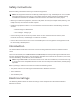
Safety instructions Read the safety information before you install the equipment. Note: This equipment must be installed by a skilled person only. A skilled person is an installer with appropriate technical training. The installer must be aware of potential hazards during installation and measures available to minimize risks to the installer and other people. • Before you install this equipment, disconnect all power sources (for example mains, battery, and telephone line) connected to the alarm panel.
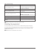
Table 1: Electrical ratings Output Rating 18 V DC, 2.2 A. DC input voltage and current Manufacturer: ShenZhen SOY Technology Co. Ltd. Model: SOY-1800222-NA Battery charging voltage and current 13.7 V DC, 500 mA Bell circuit voltage and current 11.5 V DC to 12.5 V DC, maximum current 700 mA continuous 11.5 V DC to 12.5 V DC, minimum current 700 mA Auxilliary power voltage and current Note: For 24 hour standby, the AUX current must not exceed 180 mA. PGM 1, 3, and 4 voltage and current 11.
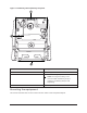
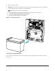
Figure 1: Breakaway tabs and battery strap slots Callout Description 1 Breakaway tabs 2 Slots for the battery strap Note: Securing the battery in the enclosure with the battery strap is optional. The battery strap is sold separately. 3 Wall tamper screw Mounting the equipment This section describes how to mount the enclosure and the external power adapter.
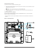
Mounting the enclosure To mount the enclosure, complete the following steps: 1. Use the four screws provided to secure the enclosure to the wall. For more information, see the highlighted areas in Figure 2. Note: Screws are provided only for the model PG9WLSHW8. 2. To enable the wall tamper, secure the tamper screw to the wall. For more information, see callout 3 in Figure 2. Mounting the power adapter You must mount the power adapter outside the PGXWLSHW8 enclosure.
Callout Description 1 Wall tamper screw 2 Enrollment button 3 Status LED 4 Power adapter mounting locations Wiring the zones You can wire zones in the following configurations: normally closed (NC), single end of line (SEOL), or double end of line (DEOL). Wiring programmable outputs You can use the programmable outputs (PGM) to activate devices such as LEDs and buzzers. To wire an output to the PGM, complete the following steps: 1. Connect the positive wire from the device to the AUX+ terminal.
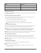
2. Clip the battery in place. 3. Optional:The battery can also be secured in place using a battery strap. To secure the battery using the battery strap, complete the following steps: Note: The battery strap is sold separately. a. b. c. d. Place the battery on the two plasic supports on the bottom of the enclosure. Insert the battery strap through one of the slots. Wrap the strap around the front of the battery. Insert the strap through the second slot.
Wiring the power supply To wire the external power supply, complete the follow steps: 1. On the power supply, secure the wires to the terminals. 2. Insert the cable through the back of the enclosure. 3. Connect the wires to the 18 VDC terminals on the PCB. Wiring the battery To wire the battery, complete the following steps: 1. Connect the red battery lead to the positive terminals on the PCB and the battery. 2. Connect the black battery lead to the negative terminals on the PCB and the battery.
To enroll the module, complete the following steps: 1. Enable enrollment through panel programming. For more information, see the panel's Installation Manual. 2. Press the enroll button on the PCB until the LED lights solid orange. Note: When you release the enroll button, the LED flashes orange to indicate that the enroll request has been sent to the panel. 3. Confirm the correct module ID (460-YYYY) in panel programming. Note: After you enroll the module, it is assigned 8 zone slots.
Table 2: Device signal strength LED color Signal strength Solid green Strong Note: For UL installations the signal strength must be strong. Attaching the cover To attach the front cover to the enclosure, see Figure 5. Figure 5: Attaching the cover Status LEDs There is one multicolored LED on the module. The following table describes the status of the module based on the color of the LED.
Table 3: Status LEDs Mode Description Turn on The LED is on while the module turns on Placement test The color of the LED shows the signal strength of the enrolled device Firmware upgrade in progress The LED is on while the system firmware updates Firmware upgrade failed The LED is on if the firmware updates fails Troubles The LED is on if any troubles are detected, excluding a tamper trouble Note: For detailed information on device troubles, see the control panel Device enrollment The LED is o
Table 4: Troubleshooting Trouble Description No battery There is no current detected on the battery terminals. Bell circuit The bell circuit is open. The load is less than 1 kΩ. Note: When you configure PGM2 for use with a 2 wire smoke detector, any troubles detected show on the panel as a fire trouble. FCC and ISED Canada Information This information applies to model PG9WLSHW8. Modification statement Tyco Safety Products Canada Ltd.
off and on, the user is encouraged to try to correct the interference by one or more of the following measures: • Reorient or relocate the receiving antenna. • Increase the separation between the equipment and receiver. • Connect the equipment into an outlet on a circuit different from that to which the receiver is connected. • Consult the dealer or an experienced radio/TV technician for help. This Class B digital apparatus complies with Canadian ICES-003.
Frequency band (MHz) Maximum power (dBm/mW) 868.7 to 869.2 12 / 15 European single point of contact: Tyco Safety Products, Voltaweg 20,6101 XK Echt, Netherlands.
2. DESCRIPTION OF OTHER RIGHTS AND LIMITATIONS • Limitations on Reverse Engineering, Decompilation and Disassembly - You may not reverse engineer, decompile, or disassemble the SOFTWARE PRODUCT, except and only to the extent that such activity is expressly permitted by applicable law notwithstanding this limitation. You may not make any changes or modifications to the Software, without the written permission of an officer of DSC.
7. LIMITED WARRANTY • NO WARRANTY - DSC PROVIDES THE SOFTWARE “AS IS” WITHOUT WARRANTY. DSC DOES NOT WARRANT THAT THE SOFTWARE WILL MEET YOUR REQUIREMENTS OR THAT OPERATION OF THE SOFTWARE WILL BE UNINTERRUPTED OR ERROR-FREE. • CHANGES IN OPERATING ENVIRONMENT - DSC shall not be responsible for problems caused by changes in the operating characteristics of the HARDWARE, or for problems in the interaction of the SOFTWARE PRODUCT with non-DSC-SOFTWARE or HARDWARE PRODUCTS.
International Warranty The warranty for international customers is the same as for any customer within Canada and the United States, with the exception that Digital Security Controls shall not be responsible for any customs fees, taxes, or VAT that may be due. Warranty Procedure To obtain service under this warranty, please return the item(s) in question to the point of purchase. All authorized distributors and dealers have a warranty program.
not allow the disclaimer of consequential damages. If the laws of such a jurisdiction apply to any claim by or against DSC, the limitations and disclaimers contained here shall be to the greatest extent permitted by law. Some states do not allow the exclusion or limitation of incidental or consequential damages, so that the above may not apply to you.