
Users Manual

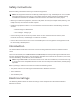
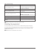
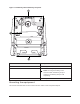
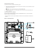
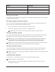
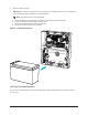
Table Of Contents
- Contents
- Safety instructions
- Introduction
- Electrical ratings
- Installing the equipment
- Enrolling the module
- Enrolling devices
- Attaching the cover
- Status LEDs
- Troubleshooting
- FCC and ISED Canada Information
- FCC class B digital device notice
- UL and ULC notes
- European CE Compliance and CERTALARM Certification
- EULA
- Limited warranty

Callout Description
1 Wall tamper screw
2 Enrollment button
3 Status LED
4 Power adapter mounting locations
Wiring the zones
You can wire zones in the following configurations: normally closed (NC), single end of line (SEOL),
or double end of line (DEOL).
Wiring programmable outputs
You can use the programmable outputs (PGM) to activate devices such as LEDs and buzzers. To
wire an output to the PGM, complete the following steps:
1. Connect the positive wire from the device to the AUX+ terminal.
2. Connect the negative wire from the device to the PGM terminal.
Note: If the device requires a current greater than 300 mA, a relay is required.
Wiring auxilliary power
You can use the auxilliary power terminals to power devices such as motion detectors and glass
break detectors. The AUX1 and AUX2 terminals provide a combined current of 700 mA.
Note: For UL and ULC combination fire and CO and burglary applications, the fire and CO
initiating devices, such as smoke detectors, heat detectors, and CO detectors, must be
powered from a separate output (AUX1) than the burglary initiating devices (AUX2).
Note: For UL and ULC installations that require 24 hour backup capacity, the maximum AUX
power load cannot exceed a current of 180 mA when using a 7 Ah battery.
Wiring the bell output
You can use the BELL terminals to power a bell, siren, or other device which requires a steady
output voltage when the system is in alarm. The panel provides a current of up to 700 mA.
Note: A 1 kΩ resistor is required across the BELL+ and BELL- terminals, or the system detects a
trouble condition.
Installing the battery
To install the 12 V/ 7 Ah battery in the enclosure, complete the following steps:
Note: The battery is sold separately.
1. Place the battery on the two plasic supports on the bottom of the enclosure. For more
information, see Figure 3.
7PG8WLSHW8 and PG9WLSHW8 PowerG Wired to Wireless Converter