
Installation Guide
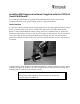
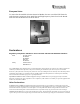

Table Of Contents

ACCESS CONTROL DIVISION
RM Installation Guide
This document is a preliminary guide to properly installing your RM1, RM2, or RM3 reader, and
assumes familiarity with the older Sensormatic MRM readers and installation procedures
contained in the apC Technical Manual, UM-009-F, the apC8/X Technical Manual, UM-010-C,
or the apC/L Technical Manual, UM-025-C.
RM Grounding
A grounding lug is provided on the RM board at J5, to which a local earth ground should be
attached. A push-on connector is provided, which should be crimped on to an 18 to 22 AWG size
wire that is connected to a suitable earth ground such as a cold water pipe or the ground
conductor at a nearby power outlet. Push the connector on to the lug at J5.
The keypad has an electrostatic discharge (ESD) tail that should go under the screw next to J5 to
provide a path to earth ground for any static discharge that may enter the RM through normal
keypad entry operation. The earth ground at J5 is essential for proper operation of the keypad’s
ESD protection layer.
Using the Auxiliary Relay Module (ARM)
Two ARMs may be connected to an RM through the P5 connector, as opposed to the single
ARM support found in the MRM series readers. P5-1 is the common pin for either ARM, and
P5-2 is the output drive for the first relay, and P5-3 is the output drive for the second relay.
Wiring from the ARM to the RM should be as follows:
ARM 1 PR-1 to RM P5-1
P2-2 to RM P5-2
ARM 2 P2-1 to RM P5-1
P2-2 to RM P5-3
SW3 Settings
1. The reader type, Wiegand or Magnetic, is set by SW3-1. The switch is preset for the type
of reader installed in the RM housing. The switch is in the OPEN or OFF position for
magnetic readers, and in the CLOSED or ON position for Wiegand output compatible
readers.
Caution – Important Static Electricity Precautions
1. Before handling any components, discharge your body’s static charge by touching a
grounded surface.
2. Wear a grounding wrist strap and work on a grounded static protection surface.
3. Do not slide the RM module over any surface.
4. Limit your movements during configuration to minimize static charge generation.