
Installation Guide
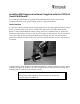

Table Of Contents

ACCESS CONTROL DIVISION
2. If an LCD display is not present, SW3-2 must be in the CLOSED or ON position. The
RM4 configuration must have the switch in this position to work properly in this
instance.
3. SW3-3 and SW3-6 control the functioning of the LEDs as follows:
a. When the internal LED bar provided as part of the RM1, RM2, or RM3 housings
is being used, both SW3-3 and SW3-6 must be in the OPEN or OFF position.
b. When an external reader is being used with an RM4 module, SW3-3 should be in
the CLOSED or ON position and SW3-6 must be OPEN or OFF to control single
or two-wire controlled bi-color LEDs.
i. For a 2-wire controlled bi-color LED, connect J4-2 to the wire controlling
the red LED, and J4-4 to the wire controlling the green LED.
ii. For a single wire controlled bi-color LED, connect J4-3 to the LED wire.
iii. For a single color LED with only an ON or OFF state, SW3-6 must be
CLOSED or ON and the control wire connected to J4-3. This connection
simulates the MRM method of tying J4-2 and J4-4 together.
4. When SW3-4 is CLOSED or ON, the tamper switch is bypassed. This switch should be
set in this position for RM4 modules as well as during testing of RM1 and RM2 readers.
5. SW3-5 is the end-of-line termination switch, and must be set to the CLOSED or ON
position if the reader is the only reader connected to an apC port or is the last reader on a
particular string of readers.
Additional Connection Pin on J3 – Pin 6
The MRMs had only five pins on this connector, which provides an interface to various reader
modules, and can provide +5V power directly to an attached reader without requiring wiring to
other MRM connectors to provide +12V power. Pin J3-6 provides the +12V power for the Indala
and Hughes modules, which may be installed in the RM, without requiring a separate wire for
the +12V.