
User's Manual
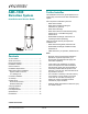


AMS-1080 DETECTION SYSTEM 8200-0418-01, REV. A
INSTALLATION AND SERVICE GUIDE
10 of 18
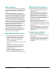
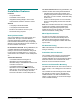
PROCEDURE
1. A label is on a bottom side panel of the AMS-
1080 antenna. The label must face the counter.
2. Attach antenna clamps.
a. Position clamps in the spaces on the
antenna designated for them.
b. A right and left spacer are provided. Press
the adhesive side of a spacer against each
clamp to hold them in place.
Note: Each spacer has a cable notch; cables
exiting the antenna pass through this notch.
If the antenna must be further from the wall
or counter, add more spacers.
IMPORTANT! Keep the antenna at
least 5cm (2in) from metal surfaces.
3. Mark mounting-screw hole locations.
a. Build the mounting base assembly by
attaching the antenna mounting bracket to
the top of the mounting base using an M5
screw, washer, and locking nut. With the
mounting base assembly in its installation
position, the bends at the top of the bracket
must face away from the counter.
b. To place antenna clamps at the proper
mounting height, temporarily insert the top of
the mounting base assembly into the slot in
the bottom of the antenna. Then holding the
antenna clamps against the counter, and
with the antenna level, mark hole locations:
• In the counter for screws that will secure
the clamps,
• Directly behind the cable notch in the
spacer where cables exit the antenna,
• On the floor for two anchors that will
secure the mounting base.
c. Remove the antenna and mounting base
assembly.
4. Drill mounting holes.
a. Using a 5.5mm (7/32in) masonry bit, drill two
holes in the floor 54mm (2-1/8in) deep for the
anchor bolts.
CAUTION: If carpet exists, use a
knife to remove it from under the
mounting base to prevent carpet
runs caused by drilling.
IMPORTANT! Holes more than
60mm (2-3/8in) deep or less than
50mm (2in) deep may not secure
anchor bolts.
b. Directly behind the cable notch in the spacer
where cables exit the antenna, drill a 16mm
(5/8in) access hole in the checkout counter
for antenna cables to go to the controller.
c. Drill holes for screws that will secure clamps.
Note: If using self-drilling screws in sheet
metal, 3.2mm (1/8in) pilot holes may be
needed. Otherwise, drill a 6.4mm (1/4in) hole
for an M5 machine screw, washer, and nut.
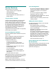
5. Install the mounting base assembly.
a. Remove the nut and washer from each
anchor and insert the anchor into a hole until
it contacts bottom.
b. Using a hammer and nail set, strike the
anchor several times to secure it.
c. Secure the mounting base assembly to the
two protruding anchors using the washer and
nut just removed. Tighten the hardware.
6. Again, set the antenna assembly onto the
mounting base and ensure the antenna is level.
7. Route antenna cables through the hole to the
controller. Connect antenna cables to the
controller. DO NOT CUT CABLES!
8. Secure clamps to the wall or counter using self-
drilling screws or M5 machine screws, washers,
and nuts supplied.
9. If used, install Ranger antennas; otherwise, see
“System Setup” on page 13.