
User's Manual
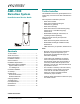


AMS-1080 DETECTION SYSTEM 8200-0418-01, REV. A
INSTALLATION AND SERVICE GUIDE
5 of 18
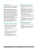
Transmit Antenna (Tx1, Tx2)
These two connectors each receive a transmit
cable from an AMS-1080 antenna.
Receive Antenna
(Rx1, Rx2, Aux A, Aux B)
Connectors Rx1 and Rx2 each receive a receive
cable from an AMS-1080 antenna or from a ferrite
(Ranger) antenna. Connectors Aux A and Aux B
each receive a cable only from a ferrite antenna.
Each connector has a Coil 1 input (top of pedestal)
and a Coil 2 input (bottom of pedestal).
These connectors default to Rx function. Any
adjustment to default settings must be saved in the
controller for use on the next power cycle or
system reset.
When using noise coils, note the following:
- A noise coil is used to cancel specific noise
interfering with detector operation.
- Noise coils only connect to the Coil 1 input of
the Aux A or Aux B connectors on the controller.
- To accept a noise coil, the Coil 1 part of each
auxiliary input must be reconfigured to noise
canceling mode using the service configurator.
- By moving a noise coil around while monitoring
power levels on the service configurator, a
location can be found where noise cancellation
is best. This is where the coil is likely to be
installed.
- The location for noise coil installation must be
practical as well as yield satisfactory results.
RS-232 Network (Service Connection)
This 4-pin modular connector receives the cable
from a modem or laptop computer used to
communicate with the controller.
RS-485 Network
This connector supports network communication
and Sensormatic alarm logging and traffic flow
devices.
Wired Tx Sync
The wired Tx sync function is used to eliminate
interference from nearby detectors and deactiva-
tors. A wired sync device connected to this port is
automatically used as the timing reference for
system functions.
Note: The controller also provides for slower
sequencer level synchronization to allow two
antennas to be placed next to each other when
driven by different controllers.