
User's Manual
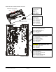
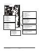
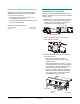
Table Of Contents
- AMS-9040 Controller
- Contents
- To the Installer
- About the Product
- Basic Operation and Setup
- Device Connections
- Transceiver (Tx/Rx) Antenna and Antenna Communication Connections
- General-Purpose Auxiliary Connections (P27, P29, P31, P33)
- Remote Alarm Connections (P7)
- Beacon Lamp Connections (P10)
- Relay Connections (P9, P12)
- Alarm Management Connection (P41)
- RS-485 Connection (P8)
- Wired Tx Sync Connection (P2)
- Wireless AC Sync Connection (On Controller)
- RS-232 Service Connection (On Controller)
- Ped (Tx) Inhibit Connection (P26)
- Installation Features
- Service Features
- Installation Requirements
- Installation Procedure
- AC Hookup
- System Setup
- Redistributing the Load
- Special Rules for Floor Antennas
- Troubleshooting
- Fuse Replacement
- Specifications
- Declarations
- Appendix A: Auto Synchronization

AMS-9040 CONTROLLER 8200-0367-02, REV. D
INSTALLATION AND SERVICE GUIDE
10 of 22
People with Implanted Medical Devices
Although this anti-theft system complies with all
applicable safety standards, place the system in
such a way that customers:
• do not linger near or lean on its antenna(s)
while making their purchase
• are only directly in front of the antenna(s) while
exiting the checkout area.
Kits and Parts Required
Bracket, extension 1 0500-9792-01
Tray, cable 1 0404-0175-02
Installation Procedure
This section describes installation procedures for
when the controller is to rest on a shelf, or attach to
a wall or ceiling.
1. Remove the cover from the top of the controller.
Then detach the cable tray/mounting bracket
assembly from the controller. Two captive ¼-
turn fasteners secure the assembly.
2. Loosen six captive screws and remove the
cover from the controller.
3. Remove knockouts closest to connectors they
are associated with.
– Only remove knockouts from the ac
connection area if the controller is to be
hardwired to ac.
– Observe requirements for Class 2 “dry” (for
low voltage devices such as remote alarms),
Class 2 “wet” for Class 2 devices that may
go somewhere other than indoors (for
example, an outdoor beacon), and Class 3
wiring. For example, antenna Tx/Rx cables
must go in a Class 3 opening but antenna
Comm cables must go in Class 2.
¼-turn fasteners (2)
Bracket
Assembly
Controller
Class 3
Class 2 DRY
AC if
hardwiring
Class 2
WET