
User's Manual
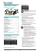
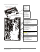
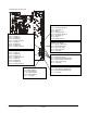
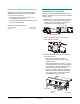
Table Of Contents
- AMS-9040 Controller
- Contents
- To the Installer
- About the Product
- Basic Operation and Setup
- Device Connections
- Transceiver (Tx/Rx) Antenna and Antenna Communication Connections
- General-Purpose Auxiliary Connections (P27, P29, P31, P33)
- Remote Alarm Connections (P7)
- Beacon Lamp Connections (P10)
- Relay Connections (P9, P12)
- Alarm Management Connection (P41)
- RS-485 Connection (P8)
- Wired Tx Sync Connection (P2)
- Wireless AC Sync Connection (On Controller)
- RS-232 Service Connection (On Controller)
- Ped (Tx) Inhibit Connection (P26)
- Installation Features
- Service Features
- Installation Requirements
- Installation Procedure
- AC Hookup
- System Setup
- Redistributing the Load
- Special Rules for Floor Antennas
- Troubleshooting
- Fuse Replacement
- Specifications
- Declarations
- Appendix A: Auto Synchronization

Device Connections
Connector pin assignments are listed on pages 4
and 5. Connectors available are as follows:
Transceiver antenna 4
Antenna communication* 4
General-purpose connections for auxiliary receive
antennas and/or noise coils**
4
Remote alarm 2
Beacon lamp 2
Relay 4
Alarm management device (UltraLink) 1
RS-485 1
Wired Tx sync 1
Tx inhibit 1
Wireless ac synchronization (Sync Link) 1
Service 1
* Each connector supports a Tx/Rx antenna and Aux
antenna, which can share the connector.
** Only Coil 1 inputs support noise coils.
Transceiver (Tx/Rx) Antenna and
Antenna Communication Connections
Transceiver antenna connectors and antenna
communication connectors support the following
Tx/Rx antennas:
• Digital Door-Max™*
• Digital Floor-Max
®
*
• Digital Pro-Max
®
Family*
• Digital Euro Pro-Max*
• Ultra•Loop Family
• AMS-3030 and AMS-3031.
* Controller-assisted tuning applies. See page 7.
Transceiver connectors (P1, P24, P4, P35). Four
connectors support Tx/Rx antennas designated A,
B, C, and D.
• Tx/Rx A connects to connector P1.
• Tx/Rx B connects to connector P24.
• Tx/Rx C connects to connector P4.
• Tx/Rx D connects to connector P35.
Antenna communication connectors (P5, P25,
P6, P36). Four connectors support controller-
assisted tuning of digital antennas.
• Tx/Rx A / Aux A connects to connector P5.
• Tx/Rx B / Aux B connects to connector P25.
• Tx/Rx C / Aux C connects to connector P6.
• Tx/Rx D / Aux D connects to connector P36.
General-Purpose Auxiliary Connections
(P27, P29, P31, P33)
Four connectors accept up to four receive
antennas with their top coils using the Coil 1
connections and their bottom coils using the Coil 2
connections.
The general-purpose auxiliary connectors support
the following receiver antennas:
• Ranger Antennas (ZKRANGER-1 and
ZKRANGER-3)
• SkyMax Antennas
• Satellite Antennas
• Auxiliary Floor Loop Antennas (ZSLOOP-AUX)
Noise coils can also share these connectors, with
each coil using the top coil (Coil 1) connection. If
connecting a noise coil and a receive antenna into
the same connector, the top and bottom coils of the
receive antenna must share the Coil 2 connection
(done in the field by the technician switching the
antenna wire connections). Thus phase flipping is
unavailable when noise coils are used.
Antennas/coils connected to auxiliary inputs are
designated Aux A, B, C, and D. These connectors
default to Rx function with no auto detection.
• Aux Antenna/Coil A connects to connector P27.
• Aux Antenna/Coil B connects to connector P29.
• Aux Antenna/Coil C connects to connector P31.
• Aux Antenna/Coil D connects to connector P33.
ABOUT NOISE COILS: A noise coil is used to
cancel noise interfering with detector operation.
• Discrete noise coils (such as a Ranger antenna
or the top coil of a pedestal antenna such as a
Digital Pro-Max) only connect to the Coil 1 input.
• To accept a noise coil, the auxiliary input must
be in noise canceling mode set using service
configurator software. Save adjustments to
default settings if they are to be used on the
next power cycle or system reset.
• Move the noise coil around while monitoring
power levels on a laptop computer to find where
noise cancellation is best. This is where the coil
should be installed.
• The location for the noise coil must be practical
as well as yield satisfactory results.
Remote Alarm Connections (P7)
This connector can power and control up to two
remote alarms, such as a ZC30 or ZC35.
Continued on page 6
AMS-9040 CONTROLLER 8200-0367-02, REV. E
INSTALLATION AND SERVICE GUIDE
3 of 22