
User's Manual
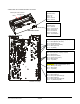
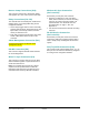
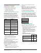
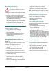
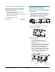
Table Of Contents
- AMS-9040 Controller
- Contents
- To the Installer
- About the Product
- Basic Operation and Setup
- Device Connections
- Transceiver (Tx/Rx) Antenna and Antenna Communication Connections
- General-Purpose Auxiliary Connections (P27, P29, P31, P33)
- Remote Alarm Connections (P7)
- Beacon Lamp Connections (P10)
- Relay Connections (P9, P12)
- Alarm Management Connection (P41)
- RS-485 Connection (P8)
- Wired Tx Sync Connection (P2)
- Wireless AC Sync Connection (On Controller)
- RS-232 Service Connection (On Controller)
- Ped (Tx) Inhibit Connection (P26)
- Installation Features
- Service Features
- Installation Requirements
- Installation Procedure
- AC Hookup
- System Setup
- Redistributing the Load
- Special Rules for Floor Antennas
- Troubleshooting
- Fuse Replacement
- Specifications
- Declarations
- Appendix A: Auto Synchronization

AMS-9040 CONTROLLER 8200-0367-02, REV. E
INSTALLATION AND SERVICE GUIDE
4 of 22
A label inside the controller identifies connectors.
Label
Cables pass into enclosure
through here.
Tx/Rx: ANT A (P1), B (P24), C (P4), D (P35)
Pin 1 - Black (Bottom coil return)
Pin 2 - Red (Bottom coil)
Pin 3 - Green (Top coil return)
Pin 4 - White (Top coil)
Pin 5 - 'X' (Shield)
GENERAL-PURPOSE AUX. RECEIVE
AUX A (P27), B (P29), C (P31), D (P33)
Pin 1 - Black (Coil 1)
Pin 2 - Red (Coil 1 return)
Pin 3 - Green (Coil 2 return)
Pin 4 - White (Coil 2)
Pin 5 - 'X' (Shield)
ULTRALINK ALARM MANAGEMENT (P41)
Pin 1 – Black (+12V return)
Pin 2 – Red (+12V)
Pin 3 - 'X' (Shield)
BEACON LAMP (P10)
Pin 1 - Black (Lamp A)
Pin 2 - Red (+12V signal lamp A)
Pin 3 - Black (Lamp B)
Pin 4 - Red (+12V signal lamp B)
Pin 5 - 'X' (Shield lamp A/B)
Continued, next page
AMS-9040 Controller
AMS-9040 Circuit Board
SERVICE (RS-232)
(Behind Cover)
Pin 1 - Rx
Pin 2 - Tx
Pin 3 - Ground
Pin 4 - Ground
SYNC LINK
(Behind Cover)
Pin 1 - Ground
Pin 2 - Sync Link out
Pin 3 - Sync Link in
Pin 4 - No Connect
Pin 5 - No Connect
Pin 6 - +5V Switched