
User's Manual
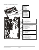
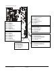
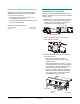
Table Of Contents
- AMS-9040 Controller
- Contents
- To the Installer
- About the Product
- Basic Operation and Setup
- Device Connections
- Transceiver (Tx/Rx) Antenna and Antenna Communication Connections
- General-Purpose Auxiliary Connections (P27, P29, P31, P33)
- Remote Alarm Connections (P7)
- Beacon Lamp Connections (P10)
- Relay Connections (P9, P12)
- Alarm Management Connection (P41)
- RS-485 Connection (P8)
- Wired Tx Sync Connection (P2)
- Wireless AC Sync Connection (On Controller)
- RS-232 Service Connection (On Controller)
- Ped (Tx) Inhibit Connection (P26)
- Installation Features
- Service Features
- Installation Requirements
- Installation Procedure
- AC Hookup
- System Setup
- Redistributing the Load
- Special Rules for Floor Antennas
- Troubleshooting
- Fuse Replacement
- Specifications
- Declarations
- Appendix A: Auto Synchronization

Beacon Lamp Connections (P10)
This connector controls up to two beacon lamps,
and supplies up to 12V at 1A to power each lamp.
Relay Connections (P9, P12)
The controller has four double-pole, double-throw
(DPDT) relays, each configurable using service
configurator software.
• These relays trigger devices such as externally
powered remote alarms and beacon lamps, time
lapse VCRs, and security cameras, with one
device per detection zone.
• Each relay connector accepts three wires and a
shield. Cable shields share one pin on the
connector.
Alarm Management Connection (P41)
Connector P41 powers an UltraLink alarm
management device.
RS-485 Connection (P8)
This connector supports RS-485 communication
for remote diagnostics.
Wired Tx Sync Connection (P2)
This connector is used to wire two or more AMS-
9040 controllers together to synchronize them to
avoid cross interference.
Note: The controller also provides for a slower
sequencer level synchronization to allow two
Digital Floor-Max antennas to be placed next to
each other when driven by different controllers.
Wireless AC Sync Connection
(On Controller)
Protected by a cover plate, this connector:
• Receives a cable from a Sync Link device
which, when connected, is used as the timing
reference for system functions instead of ac
synchronization. See “Automatic AC Line
Synchronization” on page 7. Also, see
Appendix A.
• Can also be used instead to transmit the timing
reference.
RS-232 Service Connection
(On Controller)
Protected by a cover plate, the RJ-22 connector
receives the cable from a laptop computer that is
used to locally setup and diagnose the detection
system.
Ped (Tx) Inhibit Connection (P26)
This connector has transmit inhibit pins (1, 2, 3, 4).
Each pin turns off antenna transmitter(s) assigned
to it using service configurator software.
AMS-9040 CONTROLLER 8200-0367-02, REV. D
INSTALLATION AND SERVICE GUIDE
6 of 22