
User's Manual
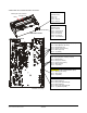
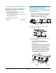
Table Of Contents
- AMS-9040 Controller
- Contents
- To the Installer
- About the Product
- Basic Operation and Setup
- Device Connections
- Transceiver (Tx/Rx) Antenna and Antenna Communication Connections
- General-Purpose Auxiliary Connections (P27, P29, P31, P33)
- Remote Alarm Connections (P7)
- Beacon Lamp Connections (P10)
- Relay Connections (P9, P12)
- Alarm Management Connection (P41)
- RS-485 Connection (P8)
- Wired Tx Sync Connection (P2)
- Wireless AC Sync Connection (On Controller)
- RS-232 Service Connection (On Controller)
- Ped (Tx) Inhibit Connection (P26)
- Installation Features
- Service Features
- Installation Requirements
- Installation Procedure
- AC Hookup
- System Setup
- Redistributing the Load
- Special Rules for Floor Antennas
- Troubleshooting
- Fuse Replacement
- Specifications
- Declarations
- Appendix A: Auto Synchronization

Installation Features
Installation features are as follows:
• Automatic detect and setup functions
• Controller-assisted antenna tuning
• Transmitter current control
• Shelf, wall, or ceiling mounting.
Automatic Detect and Setup Functions
Device Detect. The controller automatically
detects digital AM antennas when they are
connected to the controller and the controller is
powered on. Once detected, the controller sets
non-loop antennas as transceivers and loop
systems as transmit only and sets their operating
sequence as shown in the table below.
ANTENNA SEQUENCE
Digital Pro-Max Simultaneous–Alternating*
Digital Door-Max Simultaneous–Alternating*
Digital Euro Pro-Max Simultaneous–Alternating*
Digital Floor-Max Alternating only. Maximum
repetition rate is 45Hz.
AMS-3000 Simultaneous for single
antennas, Alternating for 2.
AMS-3003 Simultaneous for single
antennas, Alternating for 2.
AMS-3004 Simultaneous for single
antennas, Alternating for 2.
AMS-3010 Simultaneous
AMS-3030/3031 Simultaneous for 1 or 2
antennas, Alternating for 3
or 4 antennas
Unknown Alternating only. Maximum
repetition rate is 45Hz
(60Hz), or 37.5Hz (50Hz).**
* Simultaneous-alternating means the controller
transmits on two antennas simultaneously and then
transmits on a second pair, if they exist.
** When an antenna without device identification is
detected, the repetition rate does not exceed this
value due to the voltage rating on Floor-Max
antennas.
The controller also detects a Sync Link device,
when connected. See page 6.
Automatic ac line synchronization. To avoid
interference from nearby EAS detectors, upon
power up or system reset, the controller
automatically adjusts its:
• Operation to the ac input’s frequency and
voltage.
• Ac-timed transmit and receive functions to that
of nearby EAS transmitters, if detected.
Auto sync status is displayed on the service
configurator.
Note: If a Sync Link device is connected to the
controller, the controller uses its signal as the
timing reference instead. The service configurator
indicates that Sync Link is active.
See additional information in “Appendix A”.
Controller-Assisted Antenna Tuning
A series of LEDs on the tuning circuit board of a
digital AM antenna indicate where its tuning
jumpers are to be placed for optimum antenna
performance. The table below lists the antennas
that support controller-assisted tuning. For specific
information, see the installation guide supplied with
the antenna.
ANTENNA
Digital Pro-Max 4
Digital Door-Max 4
Digital Euro Pro-Max 4
Digital Floor-Max 4
Transmitter Current Control
The controller allows transmit current to be
adjusted as required for the region of use.
• The controller checks current in each transmitter
and the antenna coil configuration: phase
flipping, aiding, or figure-8.
• If transmit current in any antenna becomes
excessive, a signal is sent to the system’s
software. The controller also shuts down the
transmitter for one second then resumes
operation.
• Maximum operating current for each coil
configuration is as follows:
Aiding Figure 8
Non-European 16A 16A
Europe when using vertical
antennas (except Germany)
N/A 12A
Europe when using pairs of
Floor-Max antennas
16A 16A
Germany N/A 10A
AMS-9040 CONTROLLER 8200-0367-02, REV. D
INSTALLATION AND SERVICE GUIDE
7 of 22