
User's Manual
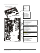
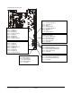
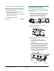
Table Of Contents
- AMS-9040 Controller
- Contents
- To the Installer
- About the Product
- Basic Operation and Setup
- Device Connections
- Transceiver (Tx/Rx) Antenna and Antenna Communication Connections
- General-Purpose Auxiliary Connections (P27, P29, P31, P33)
- Remote Alarm Connections (P7)
- Beacon Lamp Connections (P10)
- Relay Connections (P9, P12)
- Alarm Management Connection (P41)
- RS-485 Connection (P8)
- Wired Tx Sync Connection (P2)
- Wireless AC Sync Connection (On Controller)
- RS-232 Service Connection (On Controller)
- Ped (Tx) Inhibit Connection (P26)
- Installation Features
- Service Features
- Installation Requirements
- Installation Procedure
- AC Hookup
- System Setup
- Redistributing the Load
- Special Rules for Floor Antennas
- Troubleshooting
- Fuse Replacement
- Specifications
- Declarations
- Appendix A: Auto Synchronization

Mounting the Controller
Do not mount controller with its fan or
cable tray face up.
Using the cable tray/mounting bracket assembly
supplied, the controller can be mounted as follows:
• On a shelf.
• On a wall. If required, the extension bracket
provided can be used to enable mounting
screws to thread into wall studs. DO NOT mount
the controller with its fan facing up!
• To a ceiling. Plywood whose surface is larger
than the mounting bracket is first secured to the
ceiling structure that holds the drywall. The
bracket then attaches to the plywood.
Service Features
Service features are as follows:
• Laptop computer service configurator
• Internal diagnostics
• LED status indicator
• Remote diagnostics via Ethernet or RS-485
network. Ethernet requires the use of an
external converter.
Service Configurator Software
Operating software required: Windows
®
95,
Windows 98, Windows NT, Windows 2000, or
Windows XP.
Service configurator software installed in a laptop
computer is required to setup and troubleshoot the
controller. The configurator is used to:
• Set antenna coil configuration as aiding or
figure-8
• Customize detection for each antenna
• Monitor transmit and noise levels from each
antenna
• Monitor transmit current through each antenna
• Customize alarm setup
• Turn off transmitters
• Monitor temperature inside the controller
• Download new software features/updates to
flash memory
• Reset the controller after a software download
• View a system error report
• Separate a problem into one of three
categories: controller, environment, or the
device connected to the controller, such as
antennas or remote alarms.
Note: If default settings are changed, you do not
need to turn the controller off and on to store them.
Internal Protection and Diagnostics
In addition to what the service configurator
displays, the controller has the following:
• Runaway software protection.
• Board diagnostics.
LED System Status Indicator
An LED system status indicator on the controller
indicates the following:
• Green flashing (system on and okay)
• Yellow flashing (performance downgraded;
service recommended)
• Yellow or red flashing in a particular sequence
(fault detected, call for service).
The number of yellow or red flashes identifies a
digit in a two-digit alert code (for example, four
flashes is the number four). The start of an alert
code is indicated by a long LED interval. Then
the first digit of the code occurs, followed by a
short delay, followed by the second digit.
Alert codes are listed on page 17.
Remote Diagnostics
Remote diagnostics enables use of a computer at
a remote location to troubleshoot problems and
change controller parameters.
• The controller must connect to a properly
programmed modem and telephone line, or to
an Ethernet or RS-485 network.
• An external adapter is required.
Modem connections are described on page 19.
!
AMS-9040 CONTROLLER 8200-0367-02, REV. D
INSTALLATION AND SERVICE GUIDE
8 of 22