
User's Manual
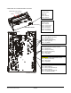
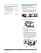
Table Of Contents
- AMS-9040 Controller
- Contents
- To the Installer
- About the Product
- Basic Operation and Setup
- Device Connections
- Transceiver (Tx/Rx) Antenna and Antenna Communication Connections
- General-Purpose Auxiliary Connections (P27, P29, P31, P33)
- Remote Alarm Connections (P7)
- Beacon Lamp Connections (P10)
- Relay Connections (P9, P12)
- Alarm Management Connection (P41)
- RS-485 Connection (P8)
- Wired Tx Sync Connection (P2)
- Wireless AC Sync Connection (On Controller)
- RS-232 Service Connection (On Controller)
- Ped (Tx) Inhibit Connection (P26)
- Installation Features
- Service Features
- Installation Requirements
- Installation Procedure
- AC Hookup
- System Setup
- Redistributing the Load
- Special Rules for Floor Antennas
- Troubleshooting
- Fuse Replacement
- Specifications
- Declarations
- Appendix A: Auto Synchronization

Installation Requirements
Installer/Contractor
• Have electrical work comply with the latest
national electrical code, national fire code, and
all applicable local codes and ordinances.
• Coordinate work with other trades to avoid
interference.
• Verify existing site conditions and coordinate
with the owner’s representative and appropriate
utilities as required.
• Obtain copies of all related plans, specifications,
shop drawings and addenda to schedule and
coordinate related work.
• Thoroughly review the project to ensure that all
work meets or exceeds the above requirements.
Bring alleged discrepancies to the attention of
Sensormatic Electronics.
If Using Conduit
• In the cable tray part of the cable tray/mounting
bracket assembly, there are three 16mm (½in)
or 21mm (¾in) knockouts for hardwired ac
power and nineteen 16mm (½in) or 21mm (¾in)
knockouts for antenna and other cables.
• Select knockouts closest to cable connectors.
• DO NOT route more cables through conduit
than regulation allows.
Power Connections
Ac power connects to the controller using a power
cord or hardwired cable. Power source can be 100-
120Vac or 200-240Vac. Controller automatically
senses the voltage so no jumper settings are
required.
WARNING—RISK OF ELECTRIC
SHOCK! The ac power cord could be
carrying 120Vac or 240Vac.
CAUTION: When using a power cord,
install a socket-outlet near the controller
in an easily accessible location.
Für Installationen mit einem Stromkabel muß
die Steckdose an einem Standort installiert
werden, welcher einfachen Zugang erlaubt.
CAUTION: A 10A, 2-pole, ganged
disconnect device, which also provides
short circuit and overload protection, and
has a minimum 3mm open circuit
clearance, in accordance with the
National Electric Code and applicable
local codes must be installed by a
licensed electrician at a location readily
accessible to the equipment.
Ein 10A, 2-poliges, gekoppeltes
Ausschaltgerät, welches auch über einen
Kurzschluß- sowie Überbelastungsschutz
verfügt, und einen minimum 3mm offenen
Schaltabstand aufweist, nach
Übereinstimmung mit den Nationalen
Elektrischen Regelungen sowie lokalen
Regeln, muß an einem Standort installiert
werden, welcher einfachen Zugang zum
Gerät erlaubt.
Mounting Limitations
• The wall must support 29.2kg (64.6 lbs) or four
times the weight of the controller assembly.
• When wall mounting, if holes in the controller’s
cable tray/mounting bracket assembly do not
align with wall studs, use the extension bracket
supplied to achieve alignment.
• Do not mount controller with its fan or cable tray
face up.
• Maximum cable length between antennas and
controller is 15.2m (50ft). Longer cables can
reduce performance and operating current.
WARNING! Do not install this product
where highly combustible or explosive
products are stored or used.
WARNING—RISK OF ELECTRIC
SHOCK! During installation, if the
antenna must be left unattended, turn off
power or cover high voltage components
to prevent unauthorized access to
hazardous voltages.
Additional Equipment Required
• Intelligent or non-intelligent antennas
(installation instructions supplied with antenna)
• Hard tag (non-deactivateable Ultra•Max tag)
and Ultra•Max low energy labels
• Laptop computer with Windows
®
95, 98, NT,
2000, or XP operating software
• RS-232 Ultra•Max programming cable
• Service configurator software.
!
AMS-9040 CONTROLLER 8200-0367-02, REV. D
INSTALLATION AND SERVICE GUIDE
9 of 22