
User's Manual


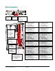
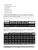


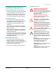
Table Of Contents
- AMS-9050 Controller
- Contents
- To the Installer
- About the Product
- Installation Features
- Setup Features
- Service Features
- Basic Operation and Setup
- Device Connections
- Installation Features
- Service Features
- - The service configurator displays the operating current for each antenna. Operating current is 15A peak for all countries.
- - The service configurator displays ambient temperature within the controller.
- - The hardware supports software with a remote command to reset the system.
- - Hardware within the controller protects it from runaway software.
- Installation Requirements
- Controller Installation
- Troubleshooting
- Fuse Replacement
- Specifications
- Declarations
- AMC-7000 Integrated Metal Foil Detection
- About this Guide
- About the Product
- Installation
- Specifications
- Declarations

Preliminary
IMPORTANT! DIP S1 and DIP S2 are located on
the circuit board of the controller. When connecting
antennas, set switches 1–8 of each DIP according
to the number and type of antennas used.
Table 1. Rules for using DIP switches
Antenna
Controller
Input
DIP S1
DIP S2
AMS-
1100/1101
Transceiver
TXA 1–4 On,
rest don’t care
Don’t Care
TXB 5–8 On,
rest don’t care
Don’t Care
TXC Don’t Care 1–4 On,
rest don’t care
TXD Don’t Care 5–8 On,
rest don’t care
AMS-1080
Tx/Rx
TXA–D 1–8 Off 1–8 Off
Rx Only RXA 1–4 Off,
rest don’t care
Don’t Care
RXB 5–8 Off,
rest don’t care
Don’t Care
RXC Don’t Care 1–4 Off,
rest don’t care
RXD Don’t Care 5–8 Off,
rest don’t care
Noise Coil 1 RXC
(top coil)
Don’t Care 1–2 Off,
rest don’t care
Noise Coil 2 RXD
(top coil)
Don’t Care 5–6 Off,
rest don’t care
For example, if using a:
- 1-2 dual pedestal exit system using two
AMS-1101 alarm antennas as transceivers:
- Set S1 switches 1–4 and S2 switches 1–4 to
“on” (switches 5–8 of S1 and S2 can be left
either on or off).
- Also ensure no receive antennas such as
noise coils are connected to the controller
when using transceivers.
- 1-2_3-4 dual pedestal exit system or 1-2-3-4
quad system using four AMS-1101 alarm
antennas as transceivers:
- Set S1 switches 1–8 and S2 switches 1–8 to
“on”.
- Also ensure no receive antennas such as
noise coils are connected to the controller
when using transceivers.
- Dual pedestal aisle system using two AMS-
1080 aisle antennas, one a transmitter, the
other a receiver: Set S1 switches 1–8 and S2
switches 1–8 to “off”.
- Noise coils: If using noise coils, turn off S1
switches 1–2 for RxC and/or S2 switches 5–6
for RxD.
Antenna alarm/Communication connectors
(P92, P93, P97, P100): Four connectors support
the antennas audio/visual alarms, transmitter/
alarms inhibit function, and peripheral RS-485
network communication.
Note: Transmitter/Alarms inhibit function and
peripheral RS-485 network communications are
only available in AMS-1101 antennas.
Receiver Connectors (P98, P99, P101, P103):
Four connectors accept up to four receive
antennas. Top coils use the Coil 1 connections;
bottom coils use the Coil 2 connections.
Noise canceling coils can also share two of these
connectors (P99, P103), with each coil using the
top coil (Coil 1) connection. If connecting a noise
canceling coil and a receive antenna into the same
connector, the top and bottom coils of the receive
antenna must share the Coil 2 connection (done in
the field by the technician switching the antenna
wire connections). Thus phase flipping is
unavailable when noise canceling coils are used.
Antennas/coils connected to receiver inputs are
designated A, B, C, and D. These connectors
default to receive function with no auto detection.
ABOUT NOISE CANCELING COILS: Noise
canceling coils, such as a Ranger antenna or the
top coil of a pedestal antenna, are used to cancel
noise that interferes with detector operation.
- Noise canceling coils only connect to the Coil 1
input.
- To accept a noise canceling coil, the auxiliary
input must be in noise canceling mode (set
using service configurator software). Save
adjustments to default settings if they are to be
used on the next power cycle or system reset.
- Move the noise canceling coil around while
monitoring power levels on a laptop computer to
find where noise cancellation is best. This is
where the coil should be installed.
- The location for the noise canceling coil must be
practical as well as yield satisfactory results.
AMC-7000 INTEGRATED METAL Foil DETECTION 8200-2609-01, REV. 3a
INSTALLATION GUIDE
5 OF 31