
User's Manual

Preliminary
AMS-9060 CONTROLLER 8200-1014-01, REV. 1A
INSTALLATION GUIDE
10 of 13
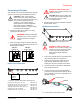
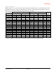
Setting Dip Switches
IMPORTANT! DIP S1 and DIP S2 are located on
the circuit board of the controller. When connecting
antennas, set switches 1–8 of each DIP according
to the number and type of antennas used.
Antenna
Controller
Input
DIP S1
DIP S2
Ultra•Exit or
Pro-Max 5
Transceiver
TXA
1–4 On,
rest don’t care
Don’t Care
TXB
5–8 On,
rest don’t care
Don’t Care
TXC
Don’t Care
1–4 On,
rest don’t care
TXD
Don’t Care
5–8 On,
rest don’t care
Rx Only
RXA
1–4 Off,
rest don’t care
Don’t Care
RXB
5–8 Off,
rest don’t care
Don’t Care
RXC
Don’t Care
1–4 Off,
rest don’t care
RXD
Don’t Care
5–8 Off,
rest don’t care
Noise Coil 1
RXC
(top coil)
Don’t Care
1–2 Off,
rest don’t care
Noise Coil 2
RXD
(top coil)
Don’t Care
5–6 Off,
rest don’t care
For example, if using a:
1-2 dual pedestal exit system using two
Ultra•Exit alarm antennas as transceivers:
– Set S1 switches 1–4 and S2 switches 1–4 to
“on” (switches 5–8 of S1 and S2 can be left
either on or off).
– Also ensure no receive antennas such as
noise coils are connected to the controller
when using transceivers.
1-2_3-4 dual pedestal exit system or 1-2-3-4
quad system using four Ultra•Exit alarm
antennas as transceivers:
– Set all S1 and S2 switches to “on”.
– Also ensure no receive antennas such as
noise coils are connected to the controller
when using transceivers.
Noise coils: If using noise coils, turn off S1
switches 1–2 for RxC and/or S2 switches 5–6
for RxD.
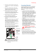
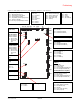
Connecting Optional Devices
Connect any optional devices to their connectors.
Relay connectors (J2): The controller has two
double-pole, double-throw (DPDT) relays, each
configurable using service configurator software.
Each relay:
Triggers devices such as externally powered
remote alarms, time-lapse VCRs, and security
cameras; one device per detection zone.
Accepts three wires and a shield. Cable shields
share one pin on the connector.
Remote alarm connector (P30, P31): These
connectors can control two externally-powered
digital remote alarms, such as an AMC-1060.
RS-485 network connector (P32): This connector
supports RS-485 communication for remote
diagnostics. It is also the connector for connecting
to UltraLink devices.
Wired Tx sync connector (P17): This connector
is used to connect an AMS-9060 controller to an
AMS-9060, AMS-9050, or AMS-9040 controller to
synchronize them to avoid cross interference.
RS-232 service connection (J3): Located on the
main board, the RJ-22 connector receives the
cable from a laptop computer that is used to locally
setup and diagnose the detection system.