
User's Manual

Preliminary
AMS-9060 CONTROLLER 8200-1014-01, REV. 1A
INSTALLATION GUIDE
2 of 13
About the Product
The AMS-9060 controller is part of an EAS system
that:
Includes Ultra•Exit or Pro-Max 5 antennas used
to detect tags/labels at exits or in food store
checkout aisles.
Deters theft by activating an alarm when an
antenna detects the unique response of an
active Ultra•Max
®
hard plastic tag or disposable
label.
The AMS-9060 controller provides the following
installation features:
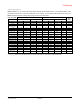
Antenna Support
The AMS-9060 controller supports up to two
(ZS9060-2) or four (ZS9060) transceiver exit
pedestals, or the same number of aisle pedestals,
each with separate transmit and receive coils.
Antennas can be set up as four transceivers, or
four transmit/receive pairs, or combinations of both
using a laptop computer and ADS 4 service
configurator software. Two receivers can be noise
canceling antenna coils. Automatic configuration is
available for the commonly used system
configurations.
Antenna coils can be set for phase flipping
(default), aiding, or figure-8 operation.
Note: Phase flipping is unavailable when noise
canceling antenna coils are used.
Alarm Support
The controller supports the following alarm
devices:
– Built-in alarm in the antenna (if used)
– Two externally-powered remote alarms such
as AMS-1060 digital remote alarms
– Up to two relays for devices such as security
cameras
– Externally-powered Sensormatic alarm
management or traffic flow device.
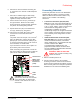
Auto Synchronization
Auto synchronization occurs during power up or
system reset. Auto sync can have different
outcomes depending on whether or not nearby
EAS transmitters are detected, they are properly
aligned to the ac-derived timing of the controller, or
too much ambient noise exists.
No transmitters detected. During initialization, the
controller determines if EAS transmitters are
nearby. If none are found, transmitter delay is set
to zero at initial power on, or set to the value stored
in the controller if not the initial power on.
Transmitters detected:
Transmitters detected and aligned. If
transmitters are correctly aligned, transmitter
delay is calculated and stored in the controller
for reference.
Transmitters detected and not aligned. If
transmitters are not aligned, transmitter delay is
set to zero at initial power on of the controller, or
set according to the value stored the controller if
not the initial power on.
Too much ambient noise. During initialization, the
controller locates other nearby EAS transmitters.
If ambient noise prevents the controller from
locating nearby EAS controllers and at initial
power on of the controller, transmitter delay is
set to zero.
If not initial power on of the controller, the zero
crossing delay stored in the controller is used.
Note: The controller stores the zero crossing delay
for when the controller could not determine a
reliable lock during subsequent power cycles.
Instead of using zero for the delay, the controller
uses the stored zero crossing delay.
Wired Synchronization
If a wired Tx sync device is connected to the
controller, the controller automatically uses its
signal as the timing reference instead of the ac
line. The service configurator indicates that wired
sync is active. See the Wired Sync Hookup
Installation Guide for wiring.
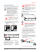
Controller Mounting
The controller has a built-in flange used to attach
the controller to a wall or ceiling using suitable
hardware.
Manual Voltage Selection
The voltage range (100-120 or 220-240 Vac) of the
controller must be manually selected at installation.
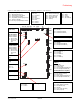
Conduit Support
Eleven knockouts receive exposed cables or
cables in conduit. Knockouts are available for
Class 2 wiring from antennas and low voltage
devices.